PolymerStrainRate_Workflow
Table of contents
Introduction
Polymer materials exhibit a wide range of properties making it difficult to generate accurate material cards for LS-DYNA. This workflow is developed in collaboration with Stellantis to enable a fully automated and accurate calibration for *MAT_024 and *MAT_SAMP_LIGHT coupled with *MAT_ADD_GISSMO cards specifically for LS-DYNA solver R10 and above. The workflow is designed for all simulation and test-engineers with minimal experience in LS-DYNA and material calibration.
The primary interaction of the user with the workflow is designed to be the START worker which can be used to input the necessary test data. The defaults of the START worker with regards to specimen type and other material properties can be updated based on the test-conditions seen in the lab.
The main specimen used by this workflow is the ISO-Type 3 with a cross-section and two main extensometers to accommodate both a digital and a mechanical measurement of the displacement and subsequent strains based on a reference length.
Pre-requisites
To use this workflow, a general overview of the Workflow applications and Workers are recommended in addition to basic introduction to Ansys LS-DYNA solver. Please contact support@d3view.com to get more information on these topics if you are unfamiliar with these topics.
Calibration Tasks
| Task ID | Name |
|---|---|
| 1 | Test data Processing |
| 2 | Hardening Curve Generation and Verification |
| 3 | Material Card Generation and Verification |
| 4 | Quasi-Static Post-Necking Calibration |
| 5 | Triaxiality based Failure Calibration (LCSDG) |
| 6 | Strain-rate dependent Post-necking Calibration |
| 7 | Strain-rate dependent Failure Calibration |
| 8 | Regularization (LCREG) |
| 9 | Verify Calibrated Material Card |
Workflow Inputs
Inputs to the workflow are classified into Required and Optional Inputs. The defaults for all optional inputs are carefully selected to work for a wide range of materials and provides the user the flexibility to change this should this be necessary. The require inputs to the workflow are listed below.
There are certain required inputs that we need to add to the workflows ‘Start’ worker to perform the basic calibration operation.
- Local Engineering Stress vs Strain curves
- These are measured on the local region of the specimen using DIC.
- Typically, the extensometer length for this measurement is chosen to be around 2-3mm
- Global Engineering Stress vs Strain curves
- This measurement is taken on the gauge length of the uniaxial coupon.
- For example, if we are using the Type 3 specimen, then the gauge length can be of 27.5 mm.
- Displacement vs time curves
- Displacement measure on the global gauge length vs test time
- Material properties:
- Elastic Modulus
- Density
- Poisson’s Ratio
Workflow Outputs
Based on the task, the workflow outputs the *MAT_ cards that can be used directly in LS-DYNA and associated PPT reports summarizing the simulation results and the overlay with the test-data.
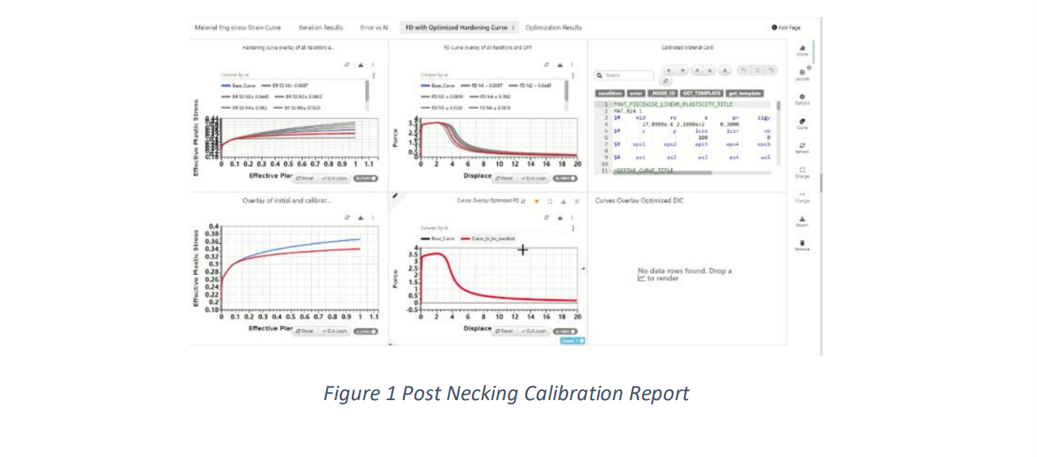
For example, as a first step, the test-data analysis and preparation task of the Workflow will provide a PPT report summarizing the test-data. In another example, if the task is to calibrate post-necking behavior, the workflow will generate an output of LS-DYNA Keyword and an associated PPT summarizing the simulation and its overlay with the test data.
Here are some example screenshots of the PPT and Keyword deck for the post-necking calibration tasks
Introduction to the Workflow User Interface
The workflow is available as part of the Workflow Library and is named as ‘013_Polymer_Calibration’. The date of update of this workflow might change based on the build and it is recommended to use the latest workflow. When the workflow is opened, the user is presented with the following of the Workflow.
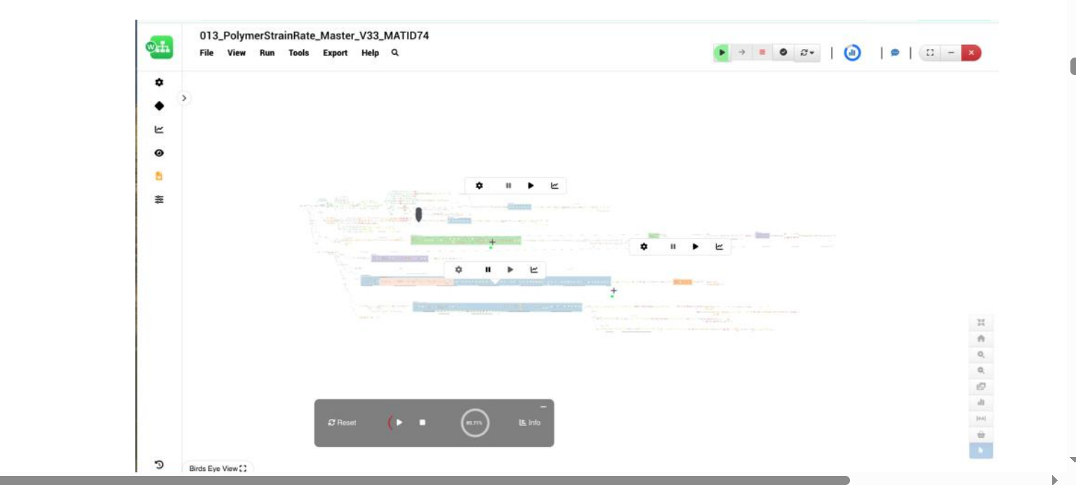
Although the workflow might appear to the complex, the interaction with the workflow is simple as the only interaction is using the START worker. The START worker provides the necessary inputs to execute the workflow and these inputs include the test-data, specimen information, and basic mechanical properties of the material such as E, RHO, NU etc.
Introduction to the START worker
The START worker is identified as shown below and contains inputs classified into Basic and Advanced. In many cases, only the Basic inputs are needed to be updated but the user is free to update the values in the Advanced section.

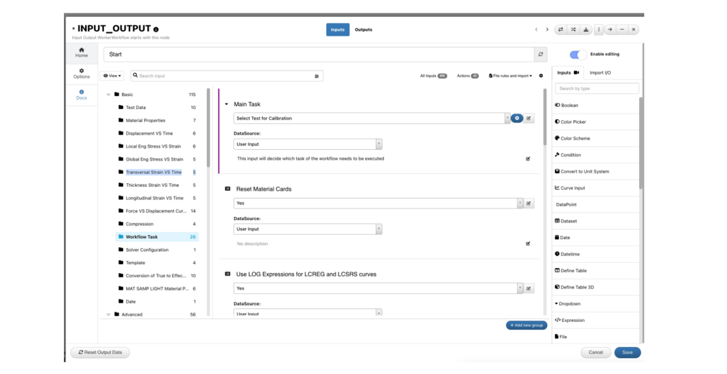
Getting Familiar with the START worker BASIC Inputs
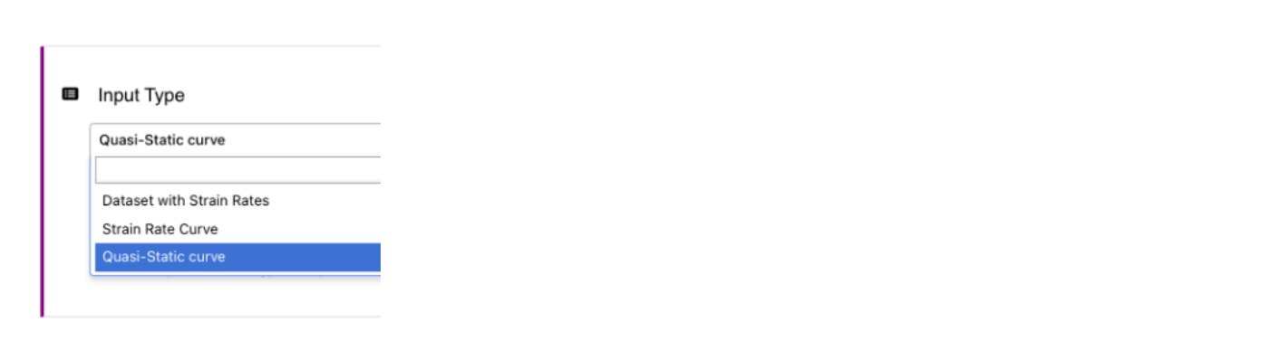
- Material Input Type
This is one of the most important input type that allows the user to specify the type of test-data that will provide to the workflow. If the available test data is only Quasi-static Tensile test, this option can be set to ‘Quasi-static Curve’. For materials with Strain-rate data, there are two options to input the strain-rate data a) Using input curves directly and specify the associated strain-rates or b) Use DEFINE_TABLE format as in LS-DYNA to define the strain-rate and the associated curves.
- Stress Strain Curves
The stress-strain curves for both Quasi-static and Strain-rates are expected to be engineering or true. The workflow is configured to convert them as needed prior to the computation of the hardening curves.

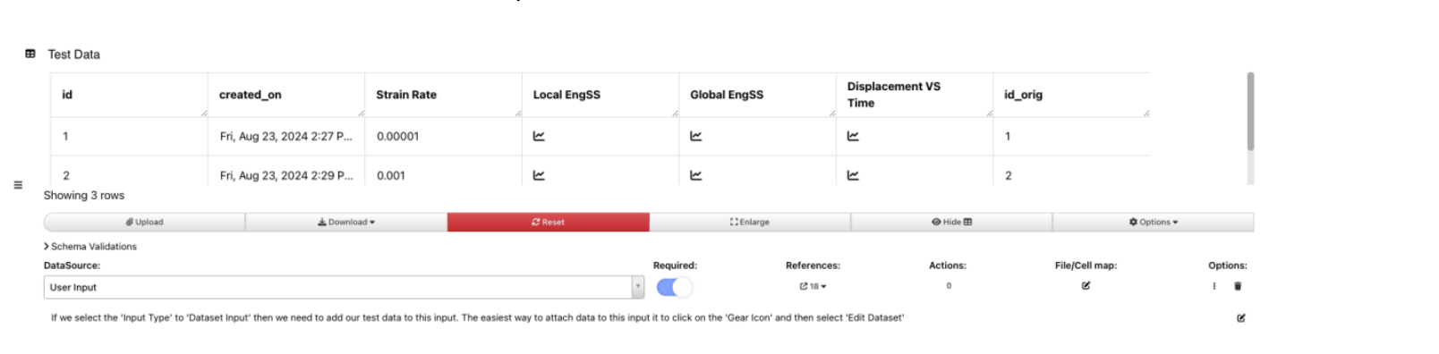
- Test Data
The test-data can be directly provided in one unified dataset that can contain the strain-rates, stress strain curves measured locally (DIC) and globally (using extensometer) and associated displacement vs time curves that can be used to load the specimen in the simulation.
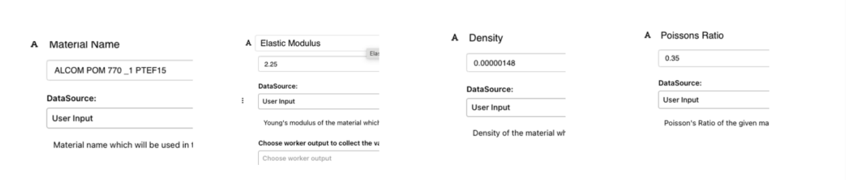
- Material Properties
The material properties such as name, modulus and density can be specified in the inputs directly as shown below. These will be directly provided to the *MAT_ cards.
- Yield Calculation
Workflow provides several methods to compute the yield value from the stress vs strain curves. The user can provide a value directly or the Workflow can be specified to compute it based on a offset or the end of linearity that is based on the limits of the linear-fit.
To accommodate the wide range of materials, each method may have its own merits and de-merits and the user is provided option to choose any of the these methods as application to the material behavior. The default option is the end-of-linearity option with the R2 limit set to 0.995

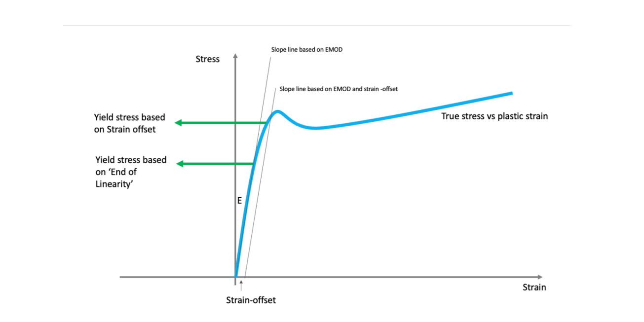
In the illustration below, we can see two types of common yield-stress calculation methods. The first one is by using a strain-offset (typically a 2% offset common in methods and a value of 3-5% for Polymers). In the second method, we can employ the end of linearity where the stress no longer has a linear relationship with the strain. The end of linearity calculation in d3VIEW is based a R2 method which is used to fit the line at every point of the curve and stop when the R2 drops below a specified value.
In a special case of yield calculation, a combination of effective stress vs plastic strain and a user-defined yield stress is used to compute the hardening curve. In the figure below, the first step is to compute the effective stress vs strain by removing the instantaneous elastic strain which is the True stress / EMOD as shown below.
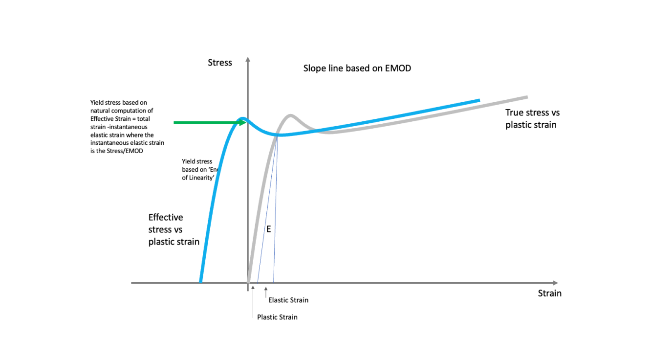
The second step involves the accounting of the user-defined yield stress. By default, d3VIEW will use the stress at the intersection of the x=0 line with the effective stress as shown below. This may work well in many cases if an accurate E is provided. Alternatively, a user-defined yield stress can replace this value a shown in the red line below. To account for abrupt changes in the derivative, another method of smoothing (green line) can be specified to smooth out the sudden change in slopes to provide a smooth hardening curve.

The correct method of yield stress depends on the material and can be calibrated to fit the test-curves
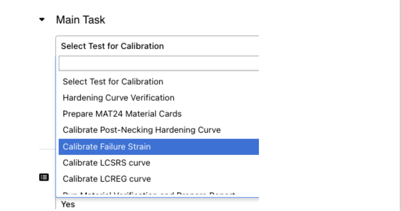
- Workflow Task
Once all the basic inputs are provided, the workflow tasks, as shown below can be used to run the workflow.
Workflow Execution
Once the START worker is populated with the required inputs, the execution panel shown below can be used to execute the Workflow. The RUN button executes the workflow and RESUME button resumes from the point at which the workflow was stopped. During the execution, the STOP button can be used to pause the execution at any time for inspection. The VALIDATE is a useful option to verify prior to execution to ensure all required inputs are correctly defined. RESET allows the workflow to be reset to its initial state. The bar icon allows to inspect the execution time of the Workflow and is helpful to capture any long-running tasks or to understand the workflow and its worker performance.

|FAQs| Frequently Asked Questions in Polymer Workflow
Can we export the Data from old polymer workflow and import it in the New version of polymer workflow?
- If we need to use a latest version of the workflow and we already have executed an old version of the workflow for few tasks, then we can export the I/O (input/output) data from old workflow and import it in the new workflow.
- This allows us to use a new version of the workflow for continuation of the calibration using the I/O data from old workflow.
- We can follow below steps to achieve import/export.
- Open the workflow from which we need to export the I/O data.
- Click on the ‘Export’ button which will give us various option.
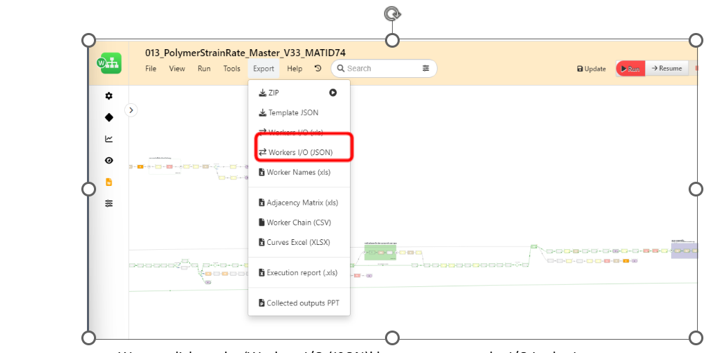
We can click on the Workers IO JSON button to export the I/O in the Json
We can now import the exported json in the latest version of the workflow using below steps
- Open the new workflow to which we wish to import the I/O data
- Click on the ‘File’ button
- Click on the ‘Import I/O’ button and select the ‘From JSON’ option
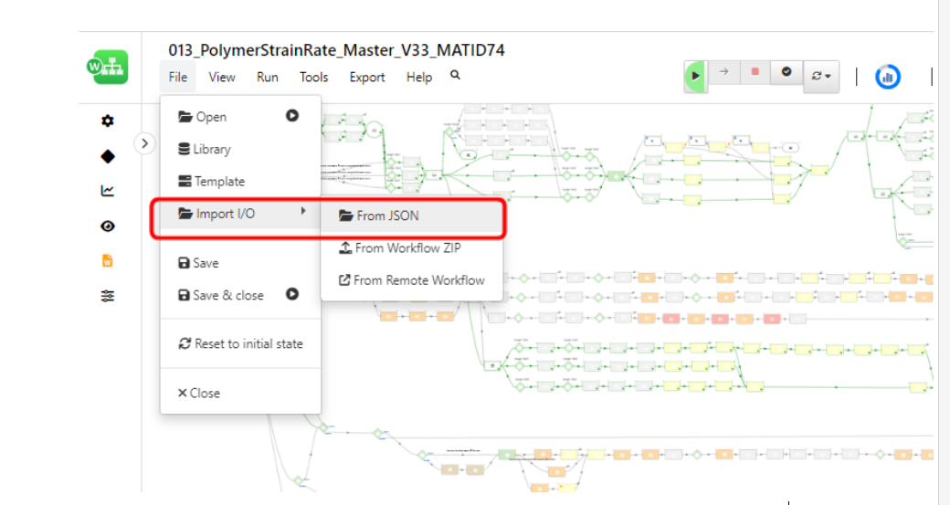
Select the json file (that we exported in the earlier steps) and click on import
Does workflow support scaling of flow curves if we do not have compression curve required for MAT_SAMPL_LIGHT material card?
- Yes, if we do not have compression curves then workflow offers the option to use scaled tension flow curve as compression flow curves
- We can follow below steps to use specify the scale factors to get the compression flow curves
- Navigate to the ‘MAT SAMP LIGHT Material Properties’ in the ‘Start’ worker.
- Set the input ‘Compression Data’ to ‘No’
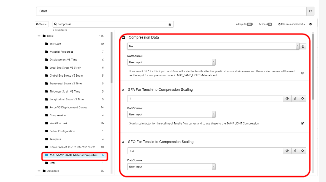
Set the SFA and SFO scale factors to scale the tension flow curves
- Alternatively, if we have the compression curves then we can simply attach these curves to the Start worker inputs available under the tab ‘Compression’
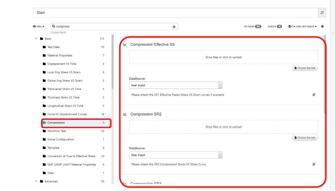
Compression
How does the workflow ensure the correct simulations parameters (Boundary prescribed motions) are created and used to submit a simulation for selected strain rate?
- Workflow is using test strain rates and maximum elongation extracted from test curves as inputs to calculate the displacement and termination time of the simulation for a particular strain rate
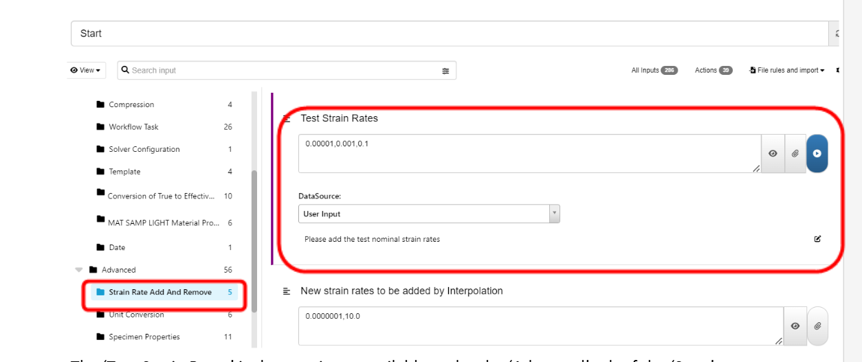
The Test Strain Rates is the user input available under the Advanced tab of the Start worker
- Workflow creates a dataset with Boundary prescribed motion parameters for each strain rate using an iterator
- The boundary prescribed motion dataset looks like below
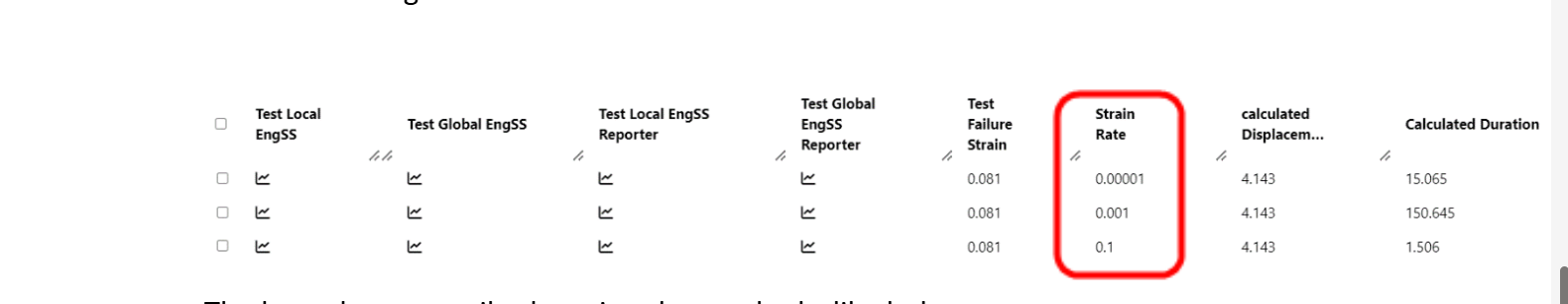
Boundary prescribed motion parameters
- Workflow pass along the required simulation parameters based on the strain rate we select for the calibration process.
Can we change the NODE IDs from which we need to extract the Extensometer measurements?
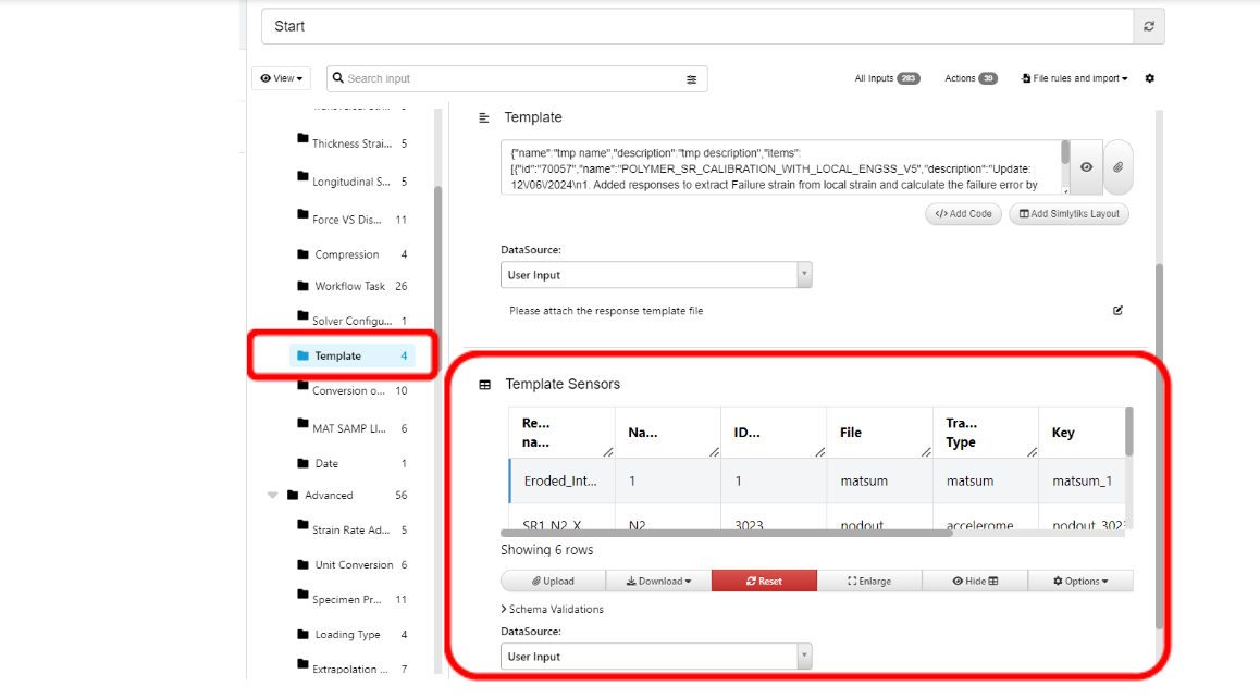
- Yes, polymer workflow allows us to configure the response template where we can edit the node ids of the extensometer
- Steps to update the sensor configuration
- Open the ‘Start’ worker and navigate to the ‘Template’ subgroup.
- Update the Node IDs under the ID column
- For Local EngSS, update the IDs of responses ‘SR1_N1_X_Coordinate’ and ‘SR1_N1_X_Coordinate’
- For Global EngSS, update the IDs of responses ‘SR1_N1_Global_X_Displacement’ and SR1_N3_X_Displacement’
Global EngSS
Can workflow handle conversion of Volumetric True Engineering Stress VS Strain curves for MAT_SAMP_LIGHT?
- In case of MAT_SAMP_LIGHT, we can add the volumetric True Stress VS Strain curves
- We will need to specify the type of input we have for the conversion of True Stress VS Strain curves
- If we have Volumetric True SS curves, then workflow expects to have the input ‘Transversal Strains VS Time’ and Thickness Strains VS Time’ to be added for the conversion of True to Engineering Stress
- To specify the type of input for we have, we can follow below Steps:
- Navigate the ‘Test Data’ subgroup and set the correct inputs for ‘Type of Input Stress VS Strain Curves’ and ‘Type of True Stress VS Strain’
- For example, if we have a Volumetric True Stress VS Strain curve, then we can select the inputs as indicated in the screenshot below
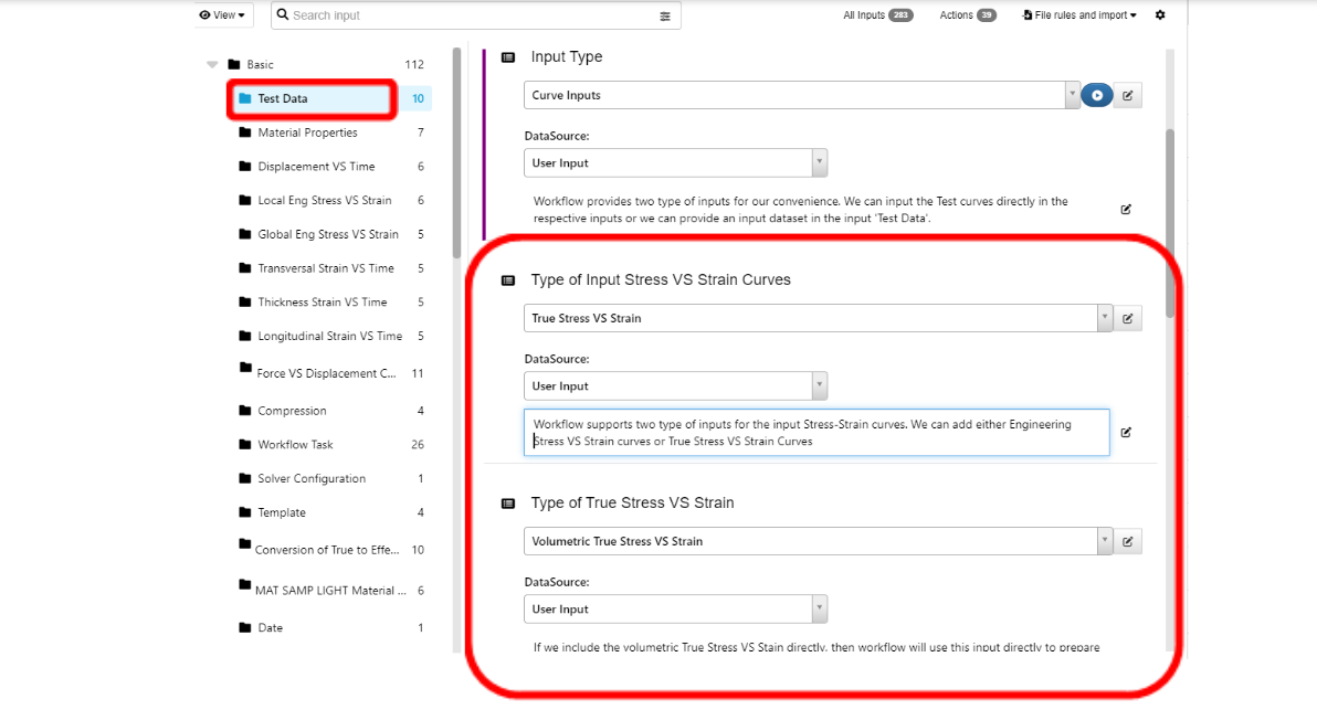
Volumetric True Stress VS Strain curve
Can we have LOG Expressions in the Material cards?
- Yes, we can add LOG Expressions for the material card.
- To activate the LOG Interpolation for ‘MAT24 and MAT_SAMP_LIGHT’ we can set the input ‘Activate LOG_INTERPOLATION’ to ‘Yes’ in the ‘Start’ worker as below
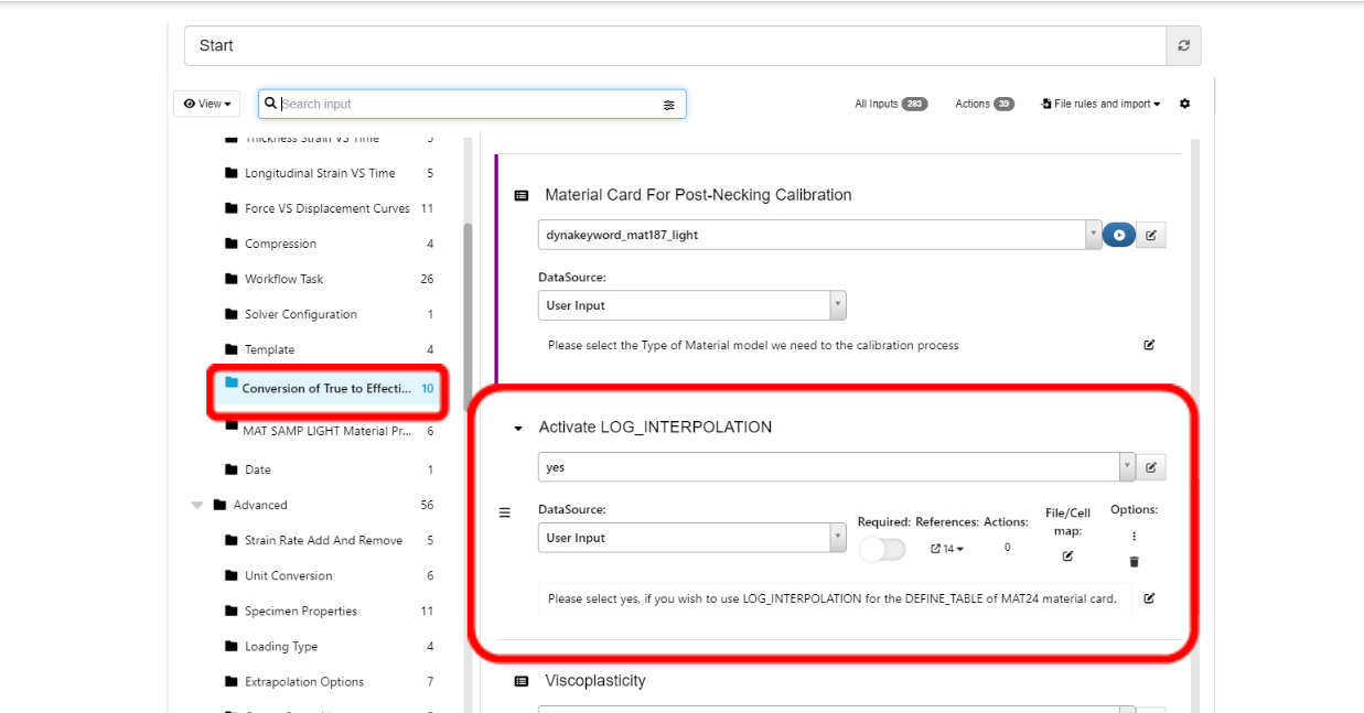
LOG Expressions in the Material cards
- Similarly, we can add log expressions for LCREG and LCSRS curves of MAT_ADD_DAMAGE Cards by set the input ‘Use LOG Expressions for LCREG and LCSRS curves’ to ‘Yes’ in the ‘Start’ worker as shown in the screenshot below.
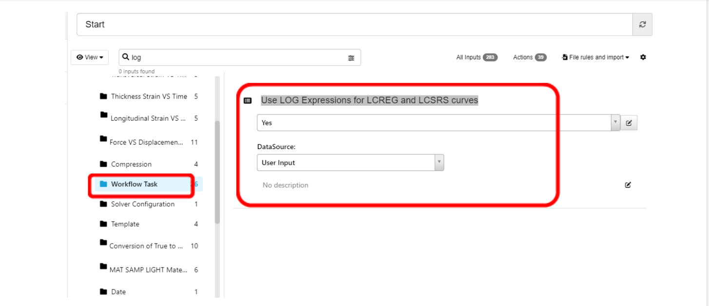
Log expressions for LCREG and LCSRS curves
References
- LS-DYNA Users Manual
- LS-DYNA Theory Manual
- d3VIEW documentation from www.d3view.com
- Crashworthiness Engineering Course Notes – Paul Du Bois and Suri Bala
- LS-DYNA Material Calibration – Suri Bala
- Technical Papers from www.dynalook.co