13. Assemblers
13.1. Assemblers in d3VIEW
AI-Powered Model Assembler with Ontology is now available in d3VIEW.
The Assembler application in d3VIEW provides an environment for managing Assemblies and creating System models with Files
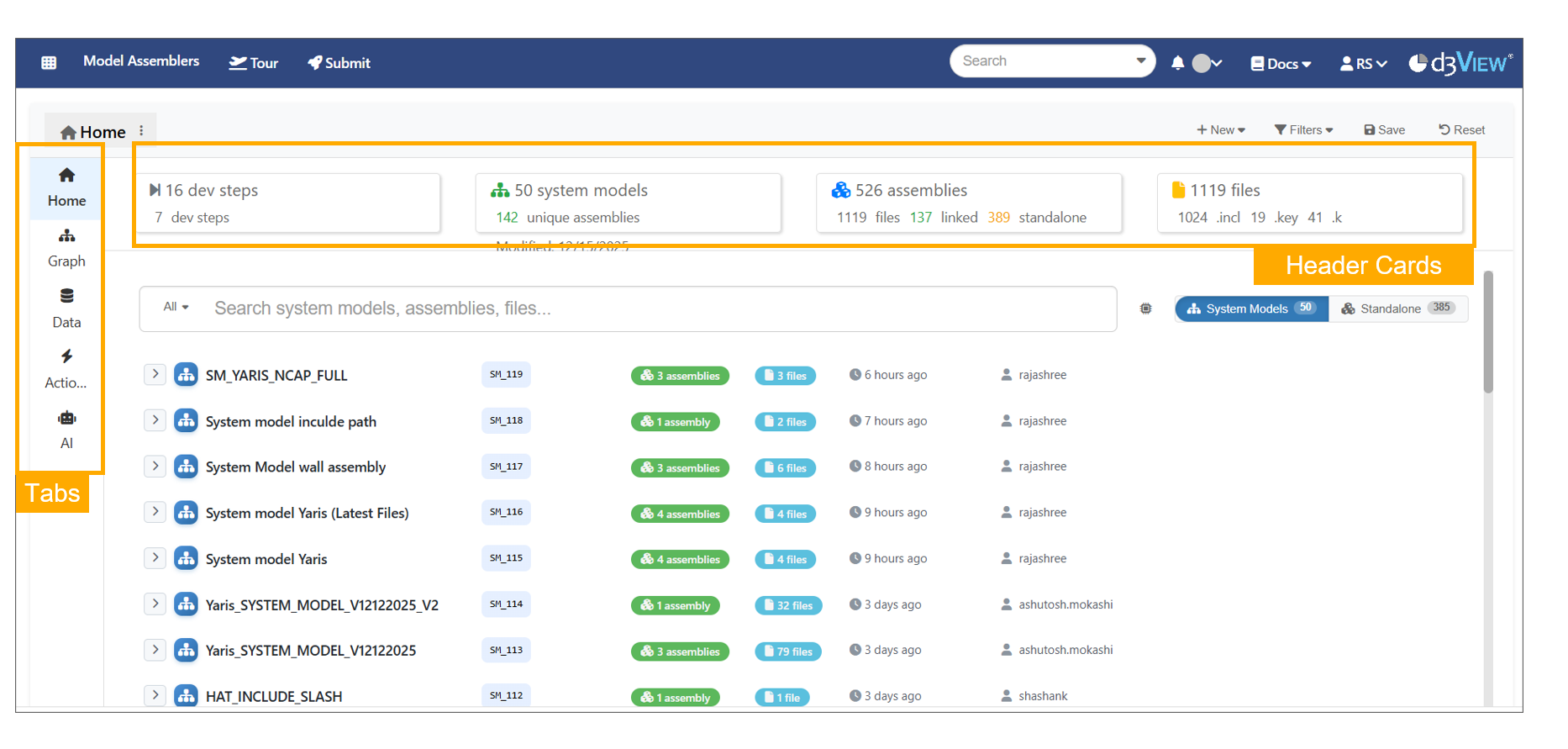
Assemblers
Assembler Models loading page has progressive steps and labels.
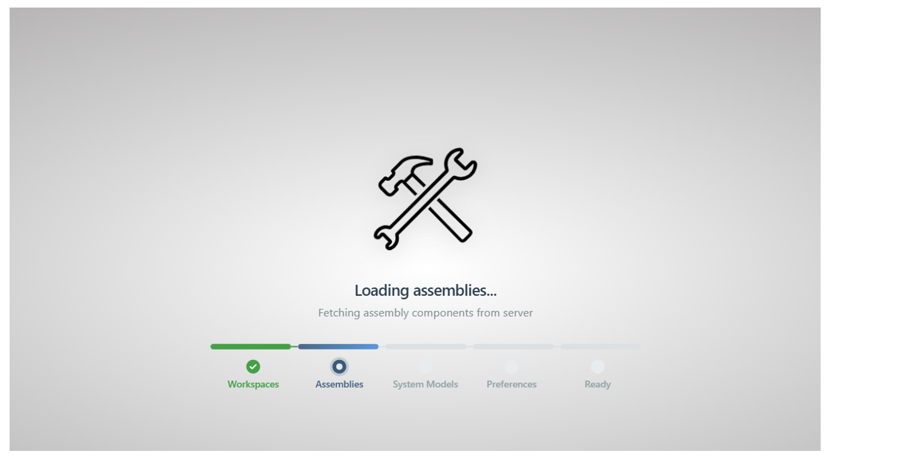
Assemblers page Loading
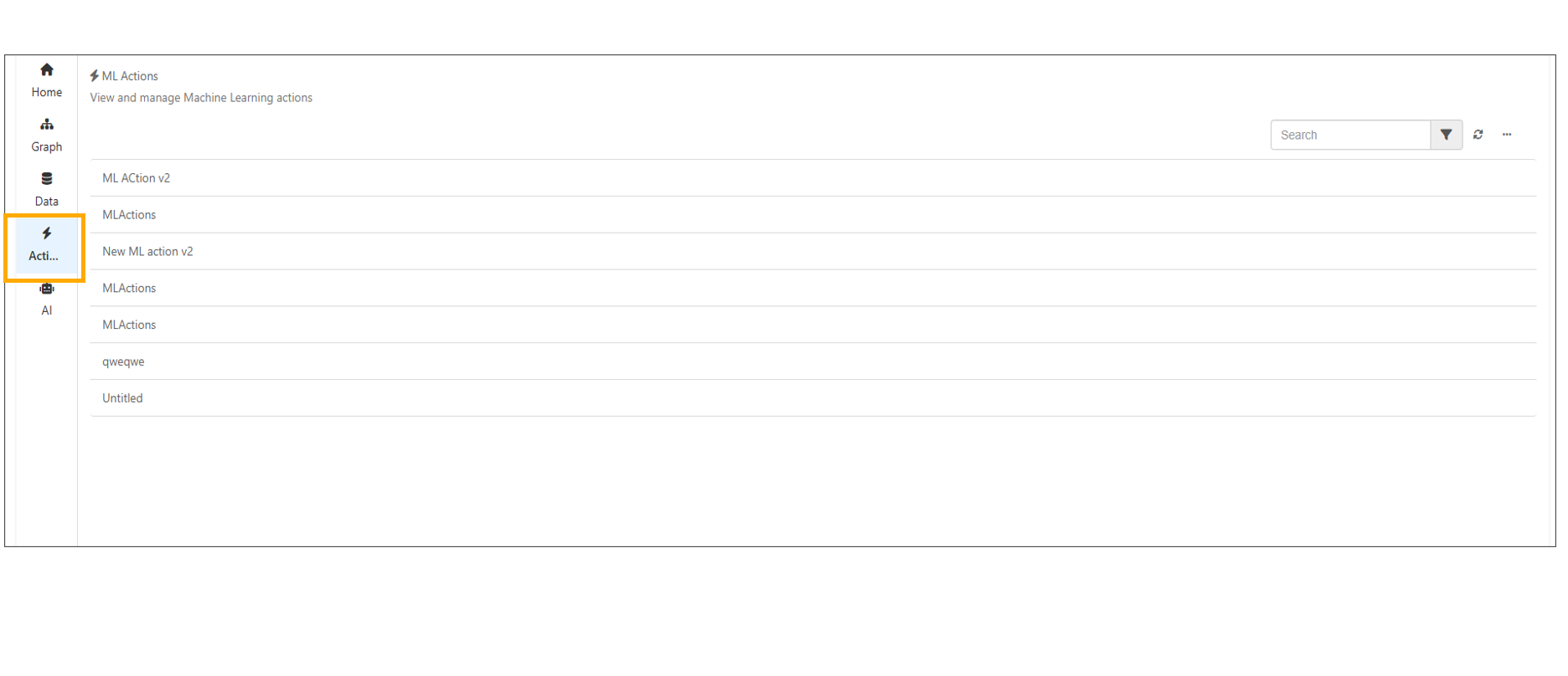
Dropdown filters are available to filter Development Steps, Models, Assemblies and ML Actions in Model Assemblers Page.
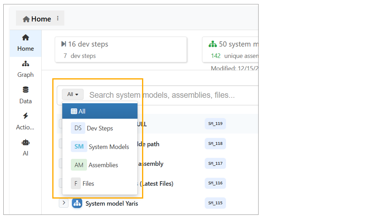
Dropdown Assemblers
System Models, Assemblies, Files, and their versions can be viewed on the Home page by expanding them.
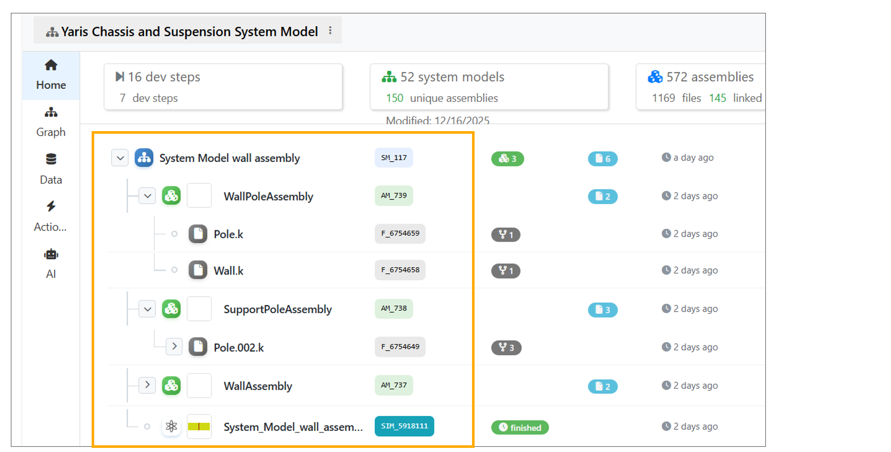
Home page expand
Reset button is available to clear all saved settings in Model assemblers page.
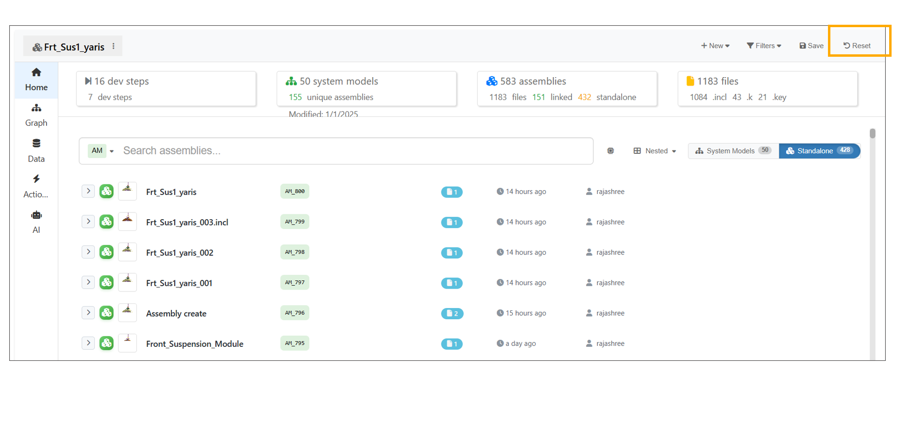
Reset Assembler
The Simulation badge on the ModelAssembler home page for System Models now displays the count of simulations and can be clicked to view the corresponding simulation details.
13.2. Project
Model Assembler now prompts users to select or create a project on launch if not selected and ensures all displayed data belongs to the active project. Users can switch projects using the ‘Select project’ option in the filters in the header.
Model Assembler homepage now adds the project as a disabled filter for records, and open tabs can be closed by hovering and clicking the close button.
Model Assembler now prompts users to select or create a project on launch if not selected and ensures all displayed data belongs to the active project. Users can switch projects using the ‘Select project’ option in the filters in the header.
Model Assembler now allows creating a new project while loading the page to render records.
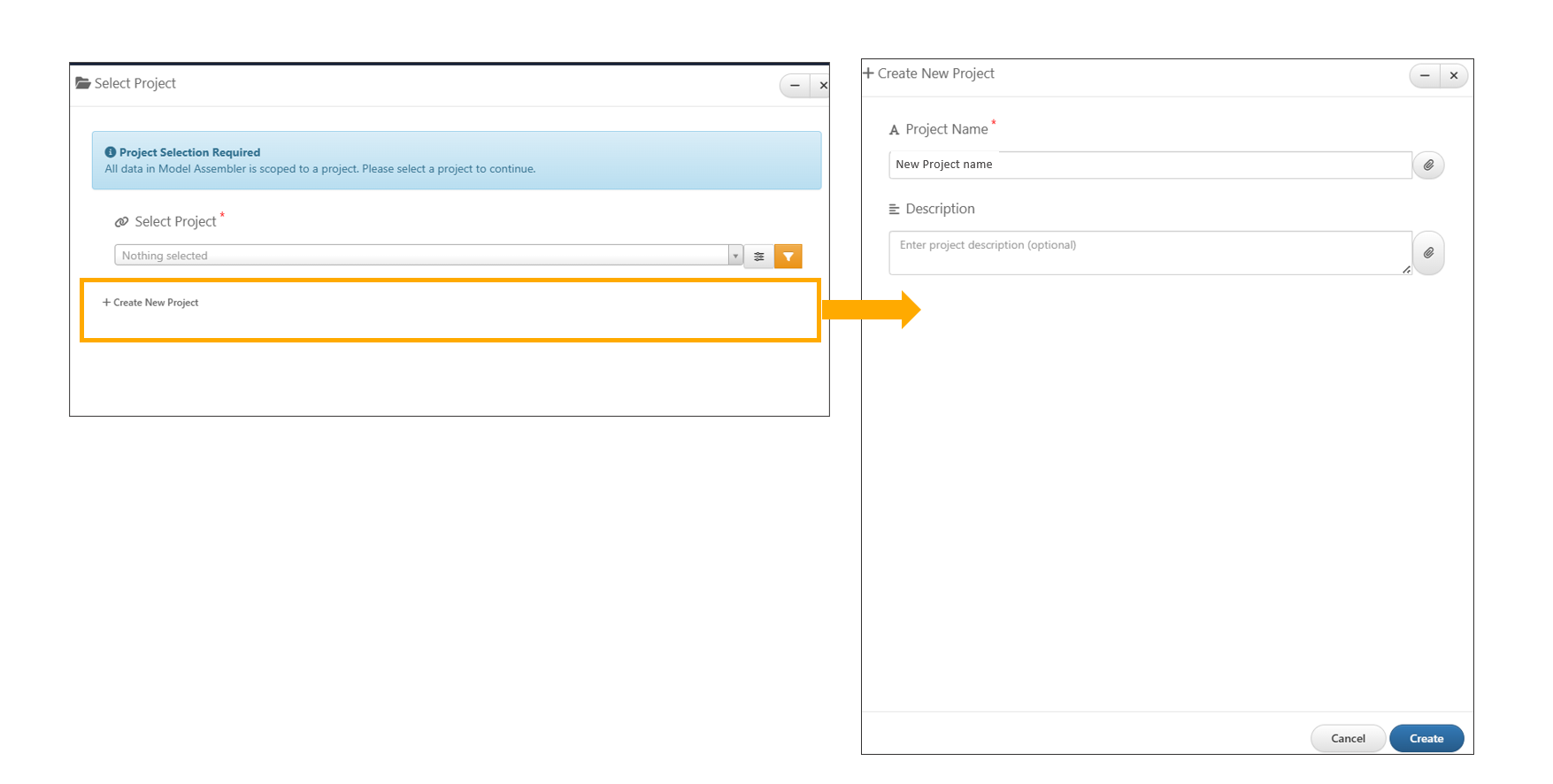
Create new project
The Model Assembler app now supports creating Projects directly from the “+New Systems” menu and introduces an option to Create separate assembly for each file during multi-file uploads, improving workflow flexibility and organization.
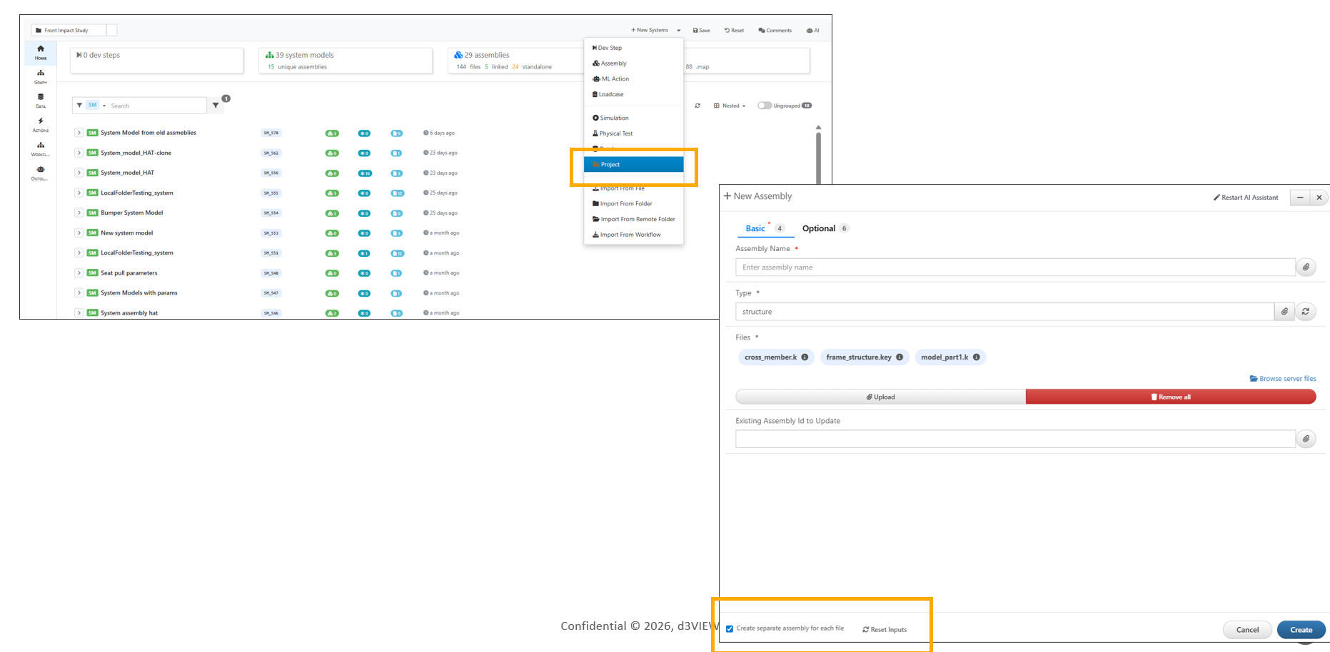
Create new project
In Model Assemblers, changing the project now displays a confirmation message on the page.
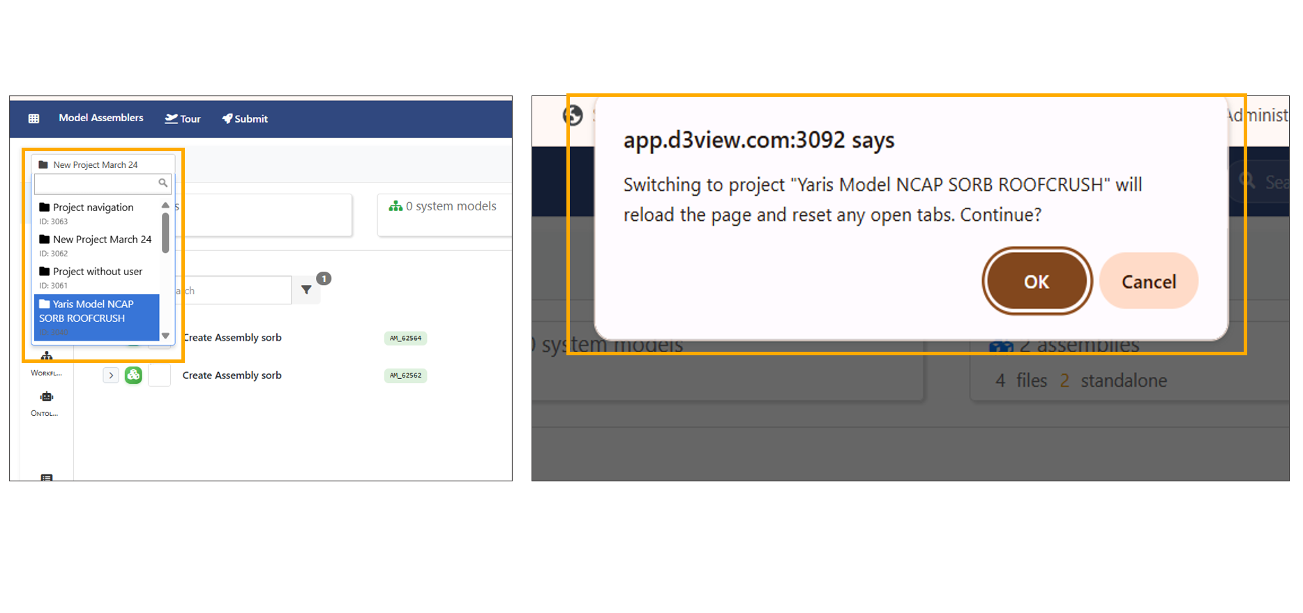
Project Switch
13.3. Search
Model Assemblers now include keyword-based search.
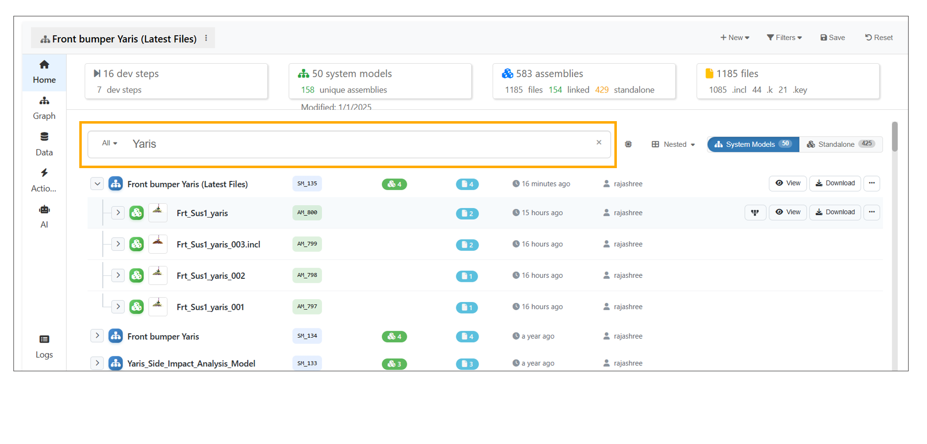
Search
Model Assembler Dashboard Search displays the dropdown filters throughout the search.
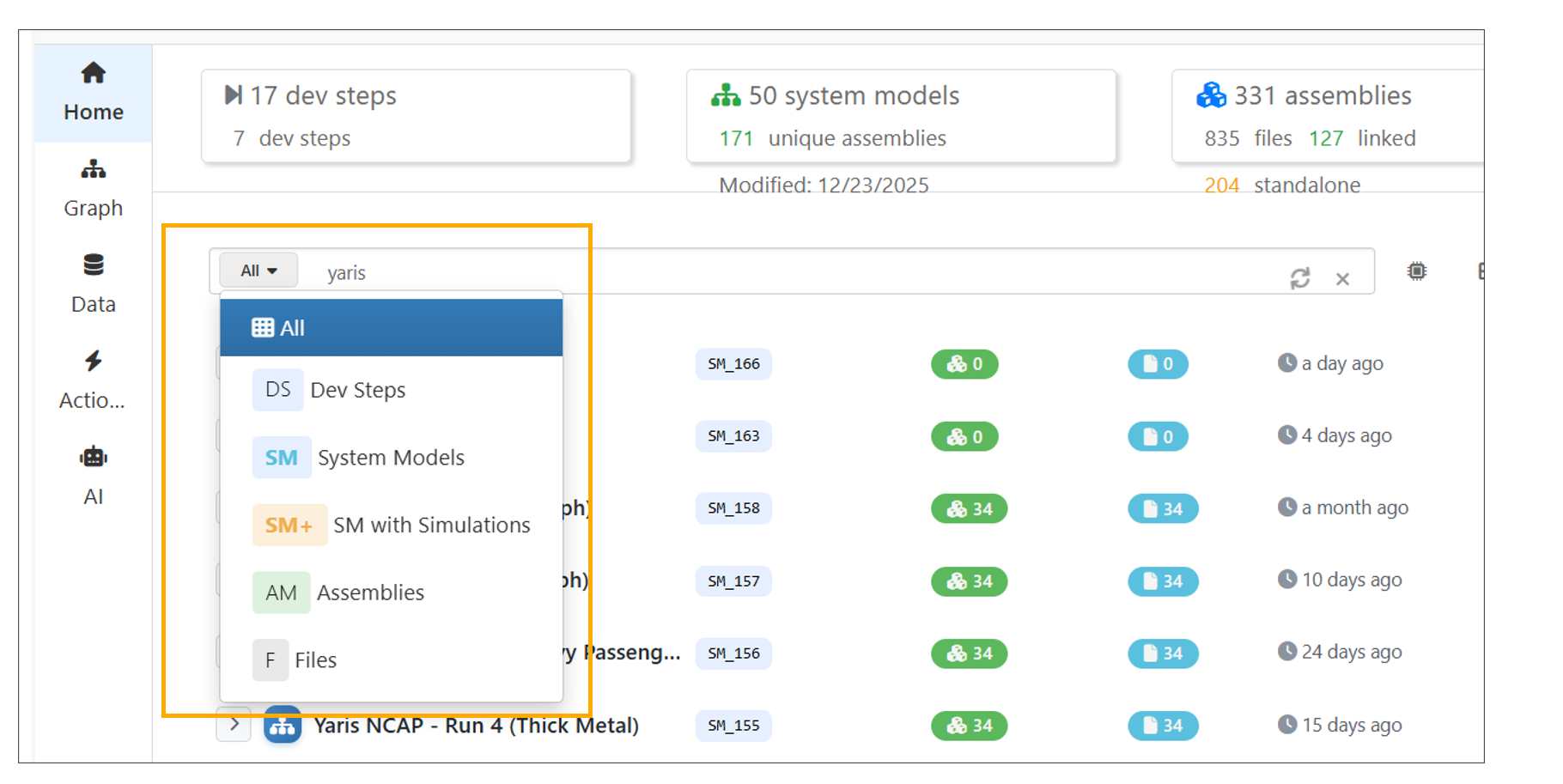
:sup:`Search `
13.4. Creation
Development Steps, System Models, Assemblies and ML Actions can now be created using the ‘New’ button in the top-right corner of the page.
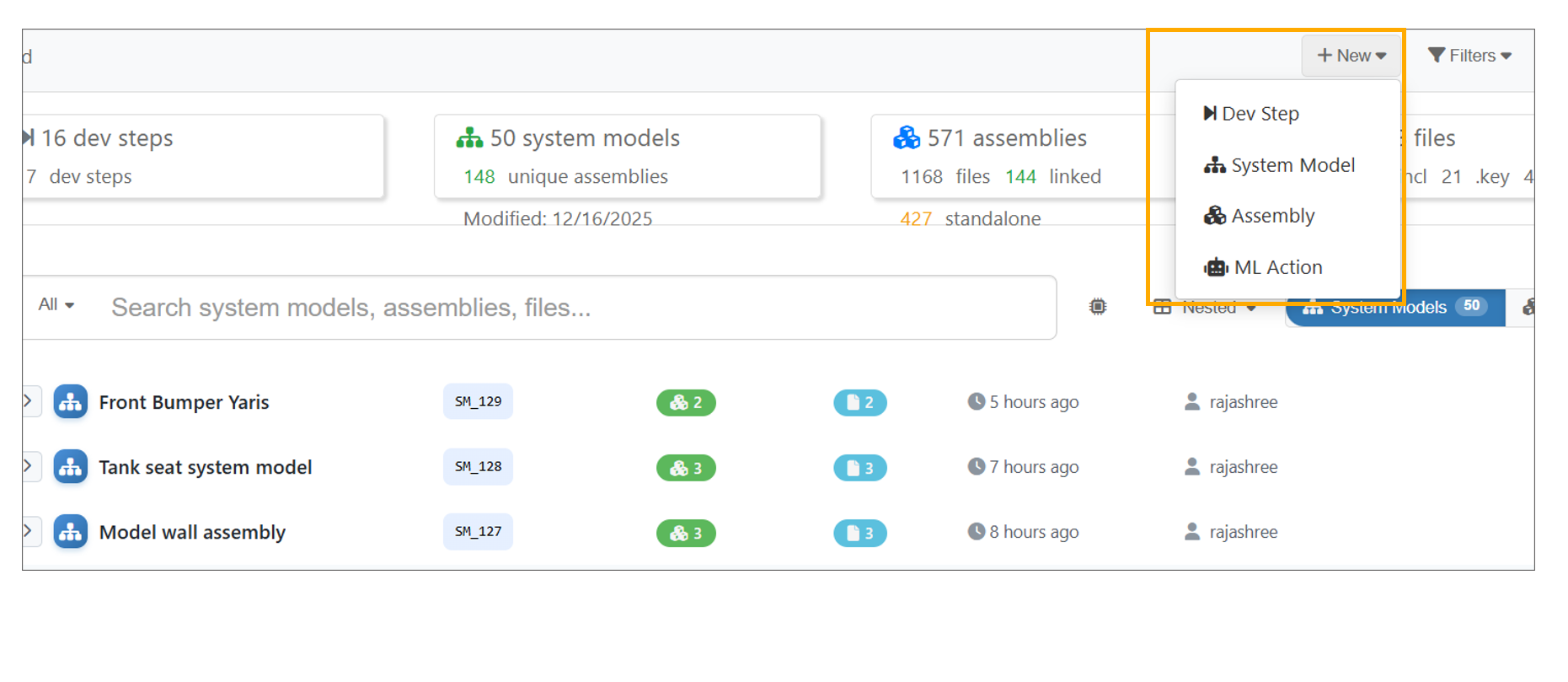
New Button
13.5. Assemblies
Assemblies can now be created using the AI Assistant.
Assemblies on the Model Assembler page is updated with tree view for all the tabs.
Open created Assembly to view files, edit them and save as a new version.
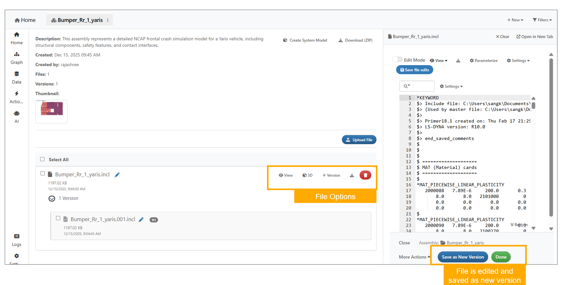
Assembler
File names in an Assembly can be edited using the pencil icon available to the right of the file name.
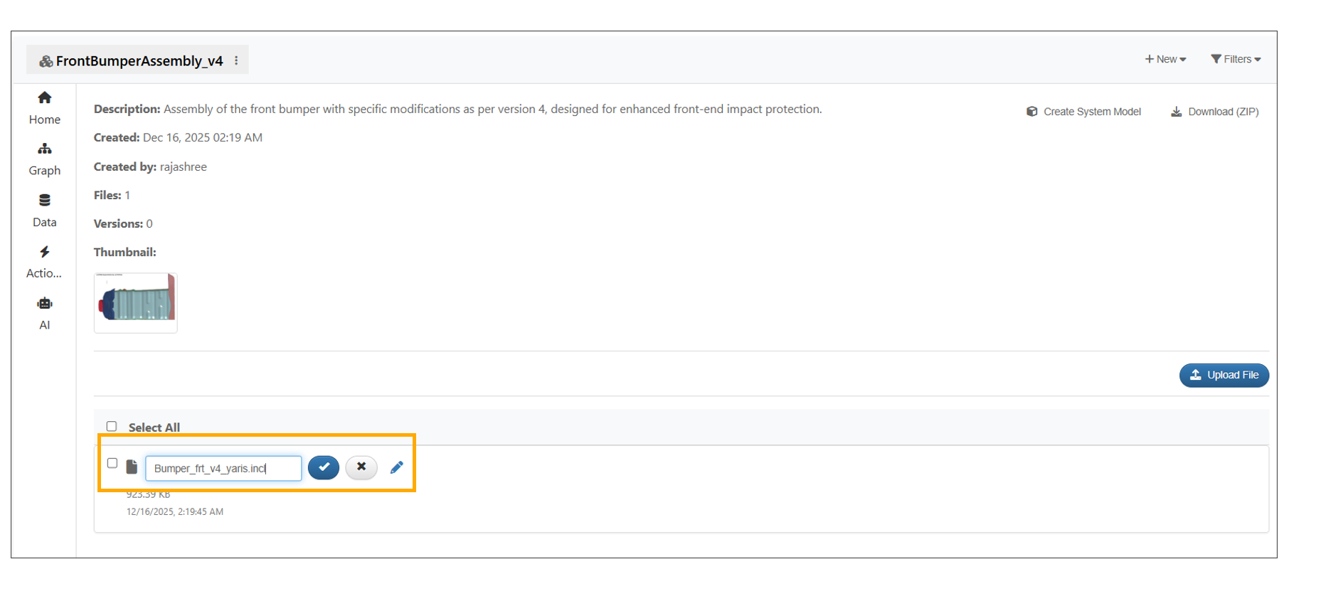
Assembler File name
In Model assembler, opening a file from an assembly now opens it in a new tab with a breadcrumb bar showing the Assembly name, File name and version.
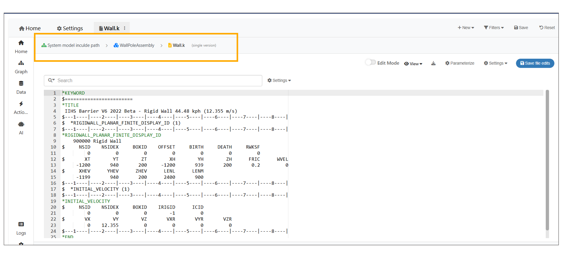
Assembler File name
Model Assembler now supports remote file browsing for Assemblies, enabling file selection from the server in addition to local uploads.
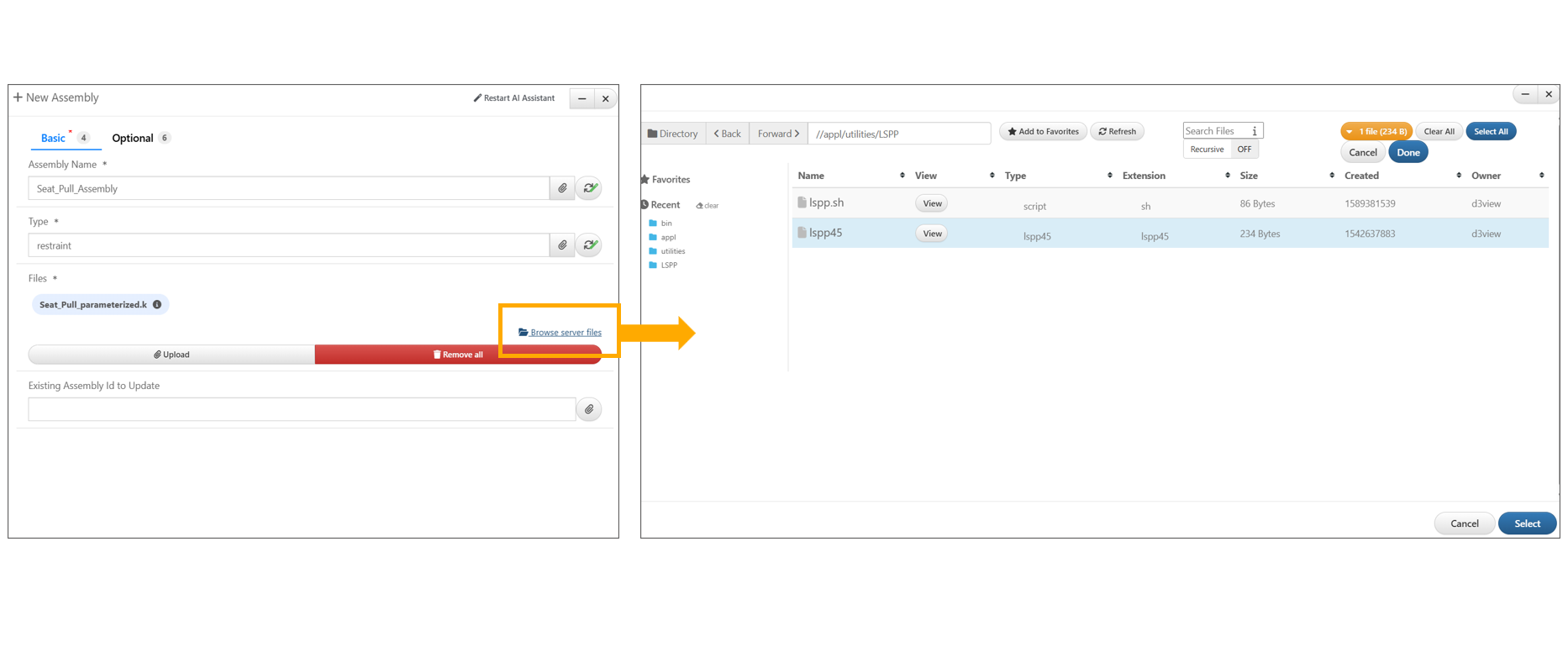
Assembler Server Files
13.6. Bom columns
The Bill of Materials (BOM) tab is now available within an Assembly’s right-side panel, loading and displaying BOM data in a table format.
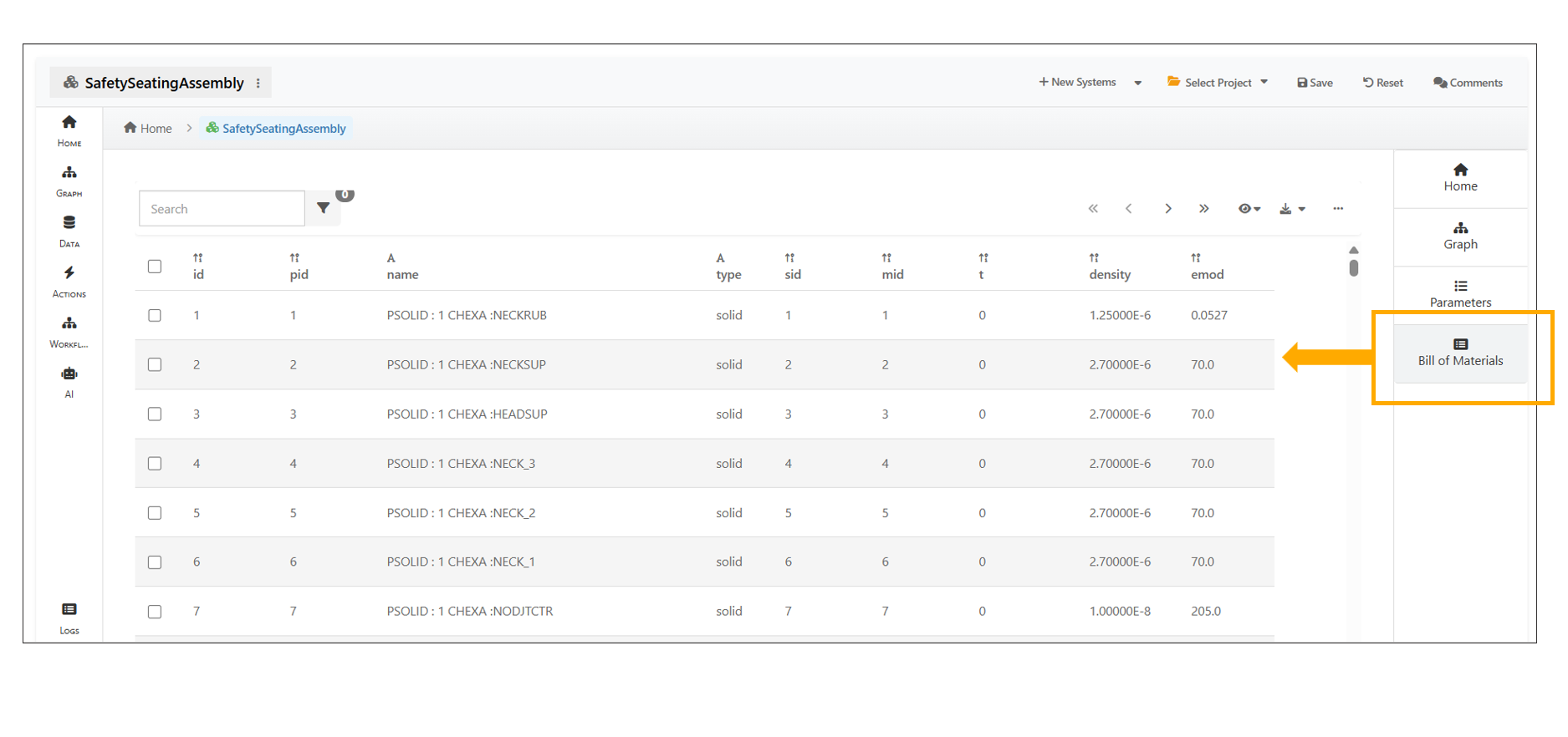
Bill of Materials (BOM)
13.7. Standalone/Ungrouped
Standalone assemblies are now available under the Ungrouped switch in the header on the Model Assemblers page, with a count badge.
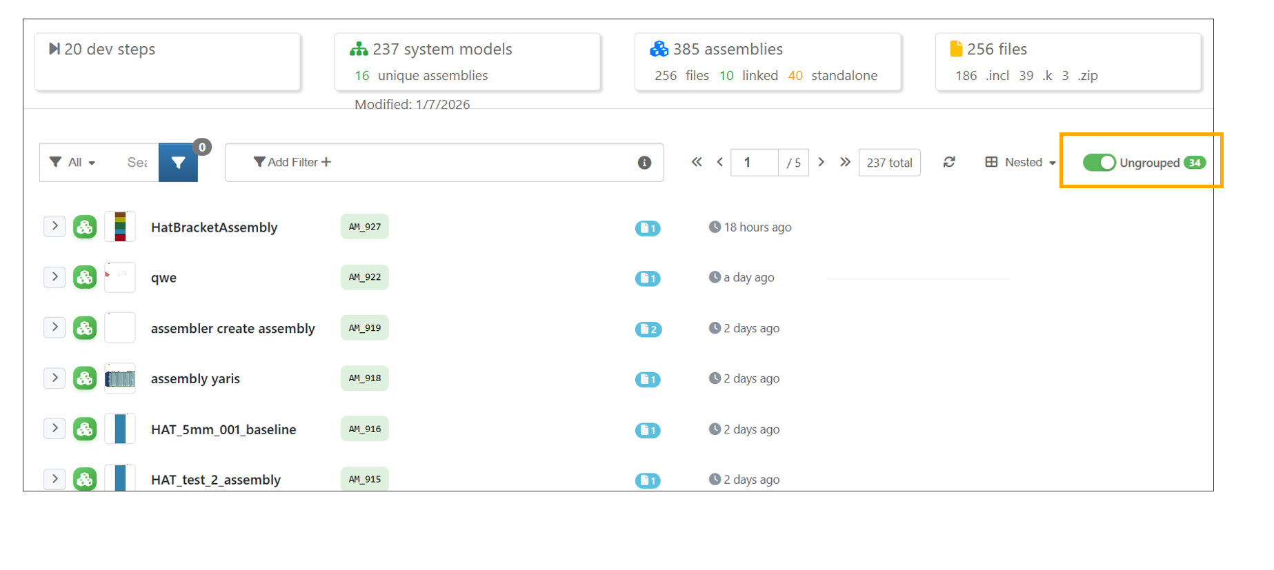
Standalone assemblies
13.8. System Models
System Models can now be created from New button.
The Model Assembler header now includes a New System button for direct system model creation, with a separate dropdown for other create options.
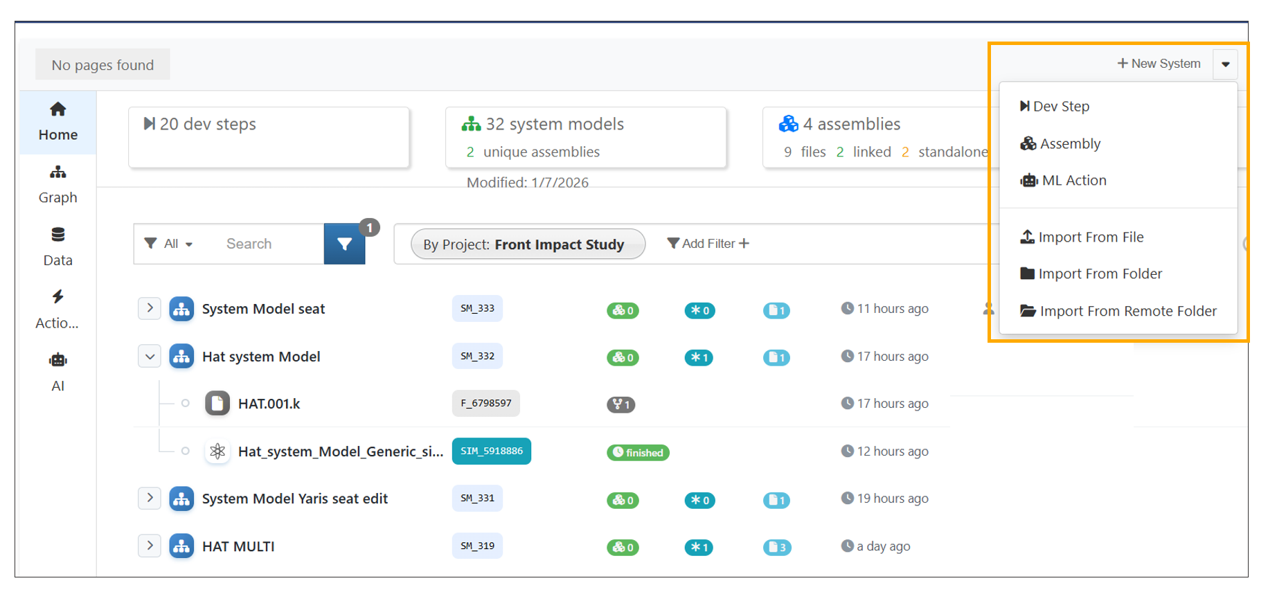
New System button
System Models can also be created using the AI Assistant.
Created System Models can be clicked to open and view the associated Assemblies.
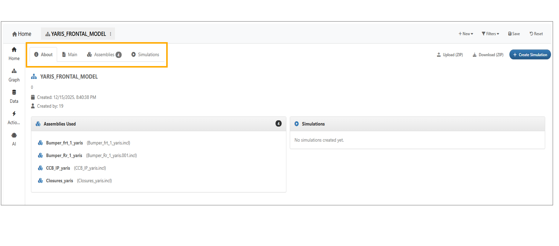
System Model
Including a path while creating a System Model will display the path in the Main file of the System Model created.
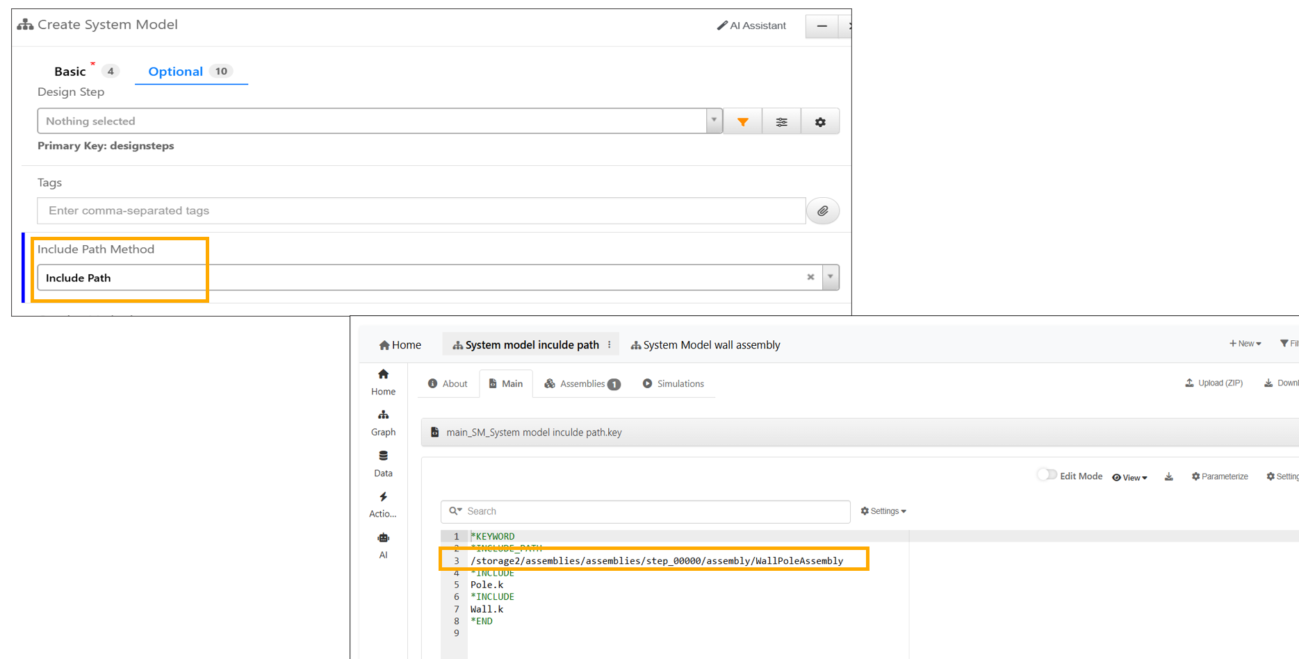
Include Path
System Models have context menu option to create a new Model using latest files from assemblies.
A new ‘Quick Clone’ context menu option is available for System Models, enabling server-side cloning of the System Model along with all its files and assemblies.
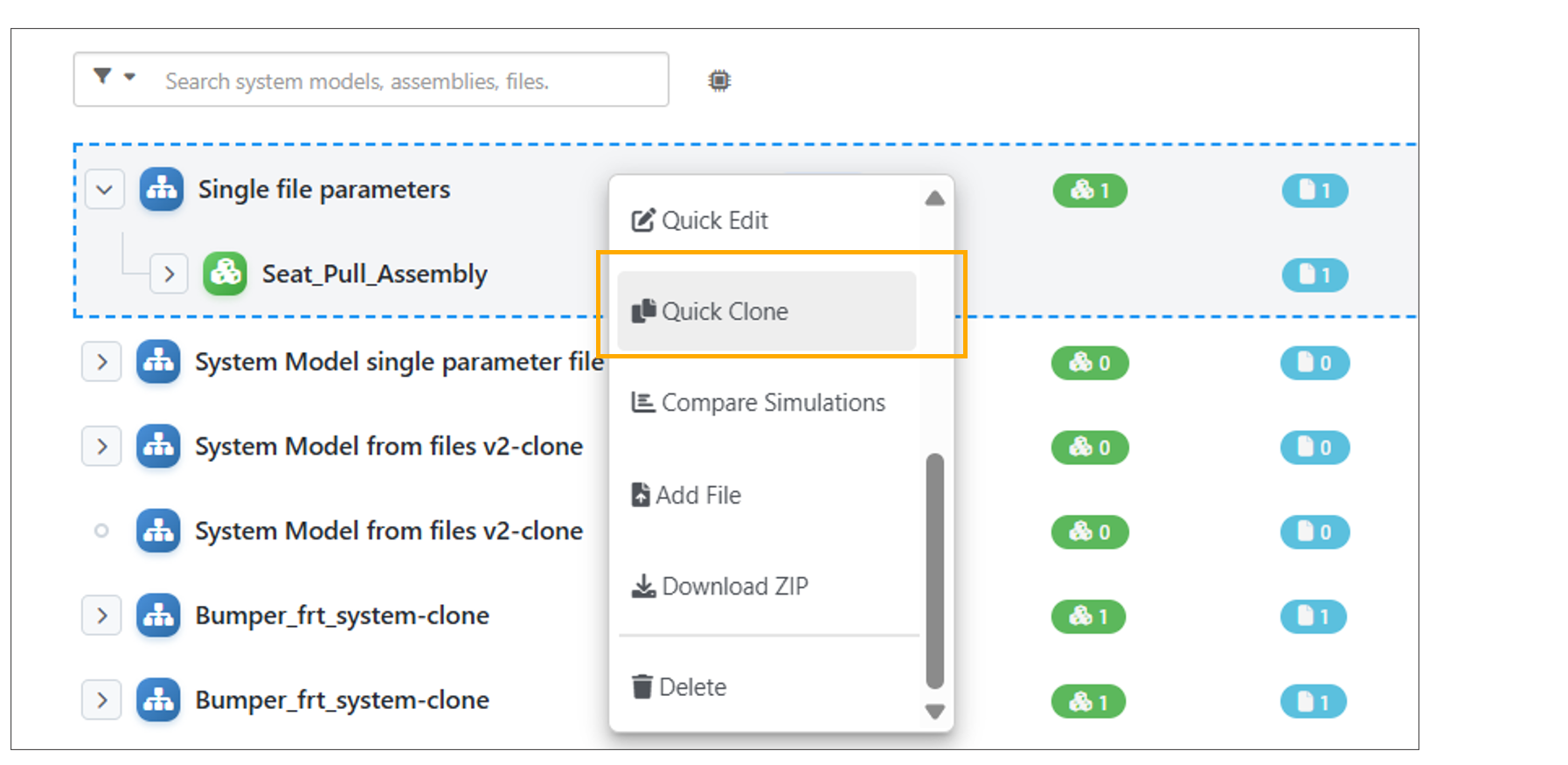
Quick Clone
13.9. System Models from direct files
System Models can be created by directly uploading files in Model assembler page.
Viewing in 3D is supported for direct file-based System Models in Model Assemblers.
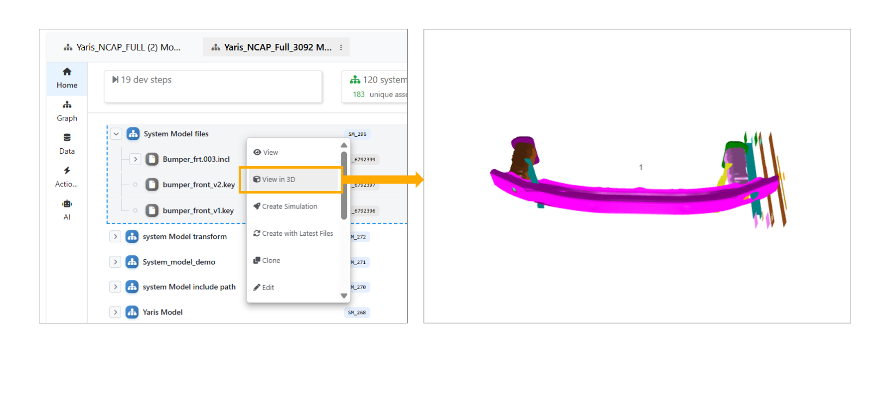
Viewing in 3D
Download as ZIP is supported for direct file-based System Models.
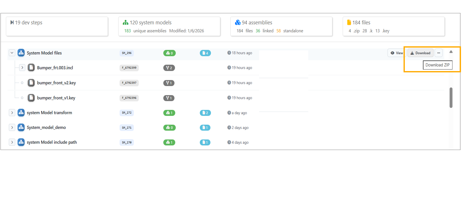
Download as ZIP
File count and Timestamp is shown for the System Models created from files directly.
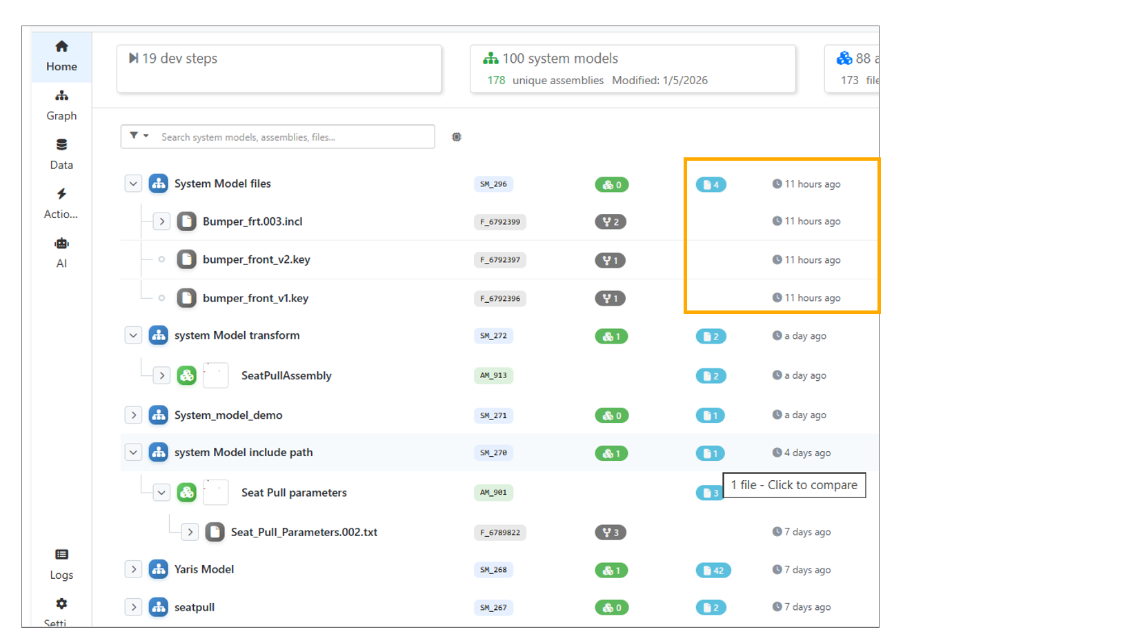
File Count
13.10. Parameters
Parameters are extracted from files added directly to System Models on the Model Assemblers page.
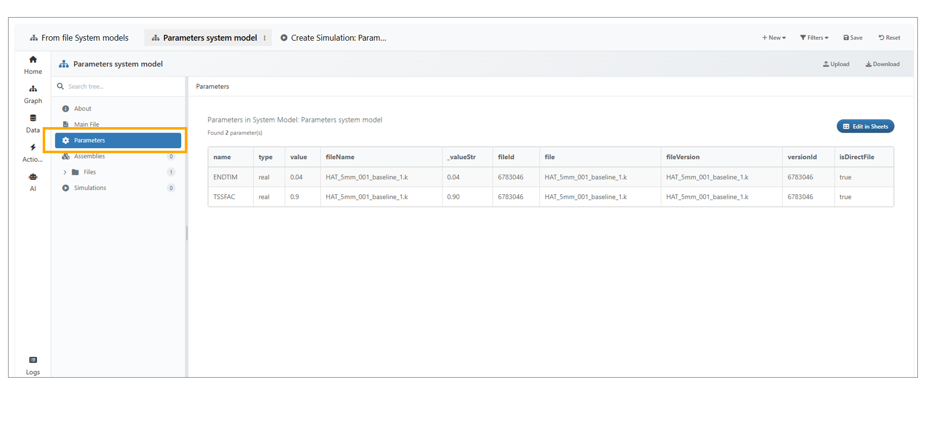
Parameters
A new option, Run DOE Using Parameters is now available in the Parameters tab under the System Model.
System Model Parameters now consolidate values across multiple files, showing the latest value, file count in “Defined In,” conflict warnings with detailed tooltips, and yellow highlighting for rows with conflicting definitions.
In Model Assembler, the DOE submission parameters step now supports discrete values, with a new ‘Discrete Values’ column where values can be entered when the parameter type is set to ‘Discrete’.
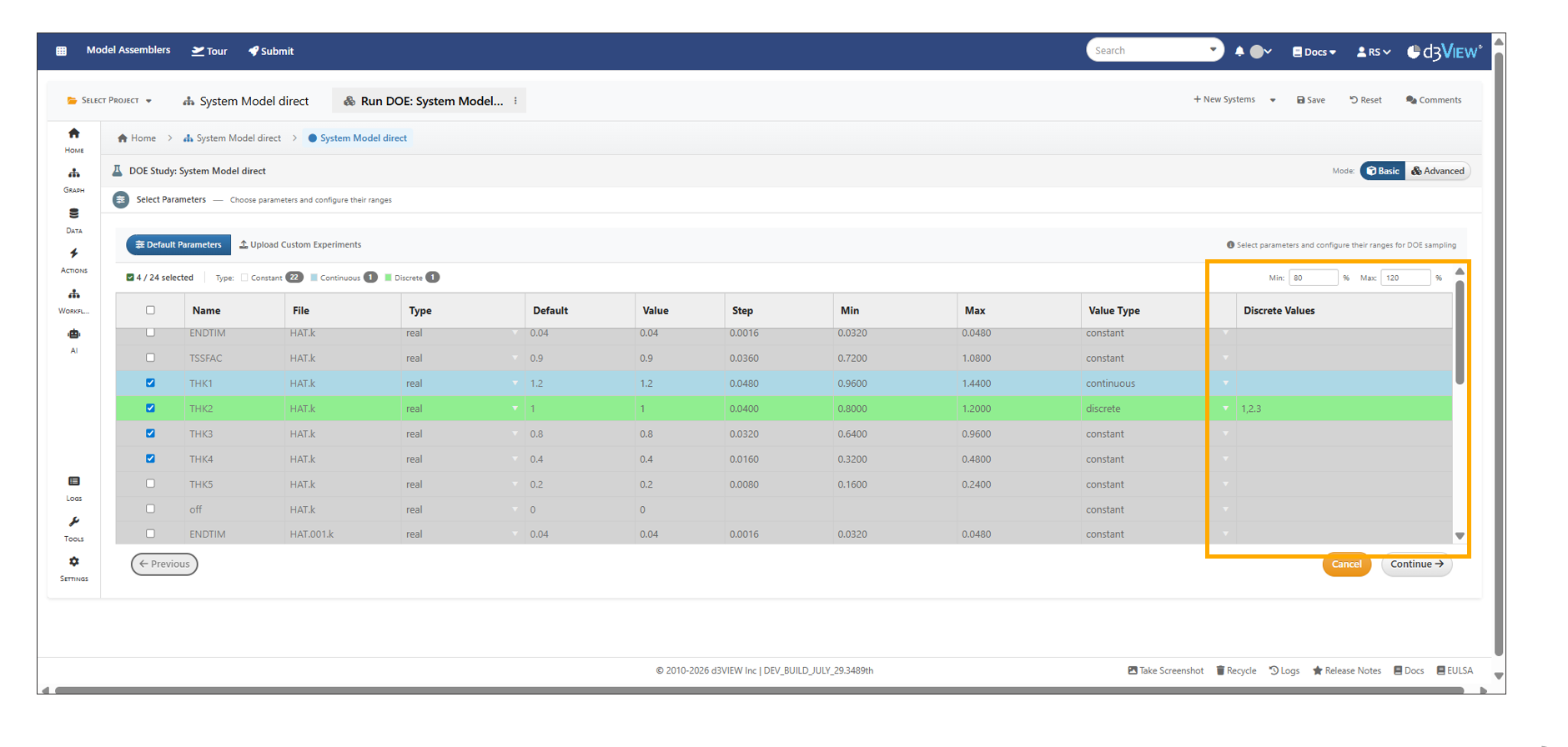
Parameters Discrete
13.11. Files
Files can now be added to a System Model directly using the context menu option in the Model Assembler page.
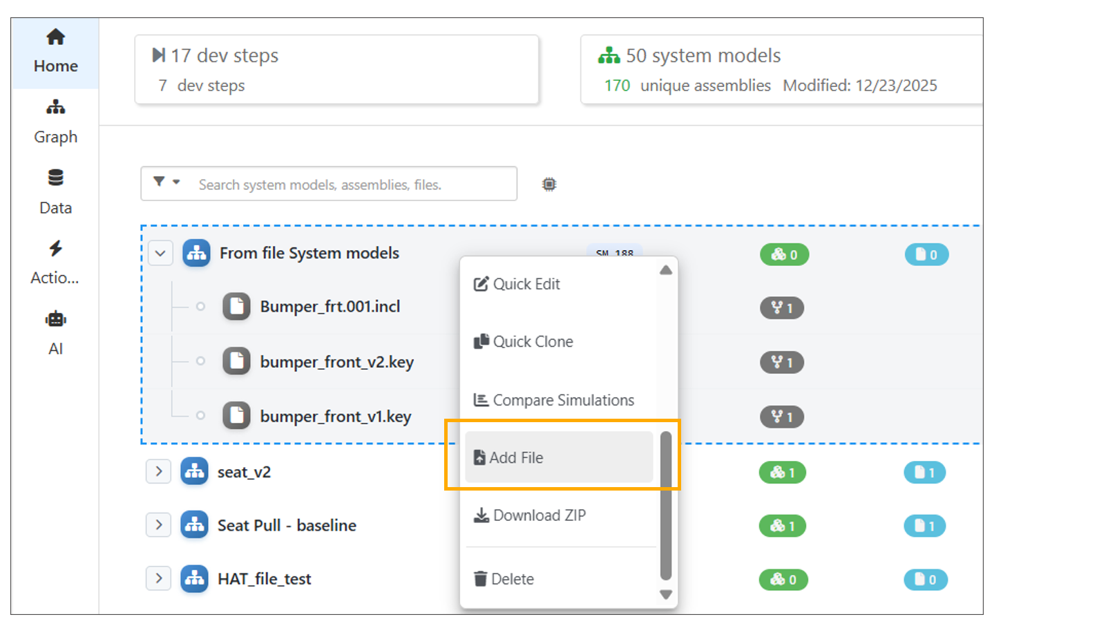
Files
Clicking a file name in the System Model opens the file and shows its contents.
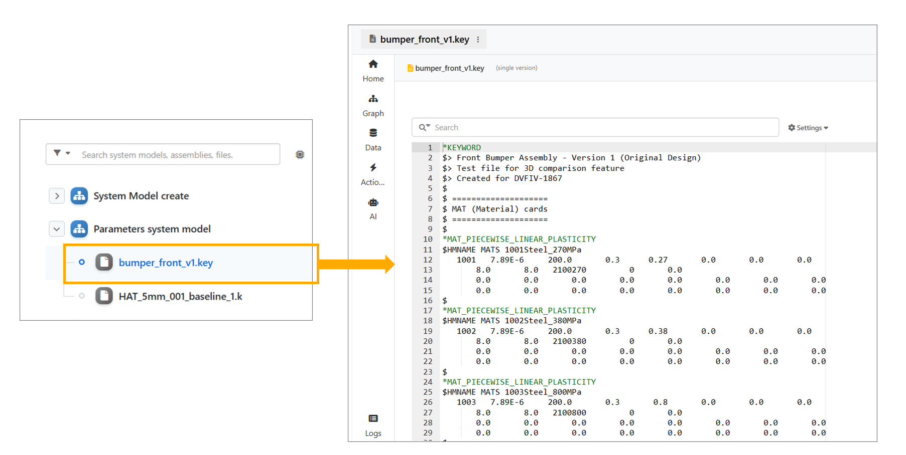
Files
System Model files can be viewed in 3D using context menu option.
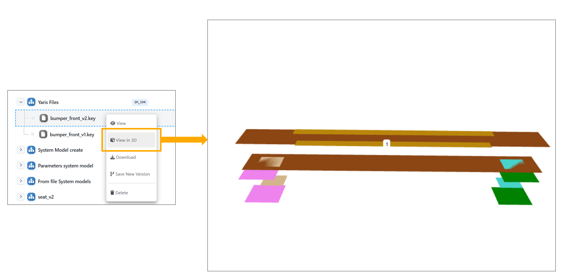
Files 3D
In System Model Files, file rows now support single and multi files removal option in the floating action bar and in context menu, with Select all, Clear selections, Merge (when applicable) and Remove options.
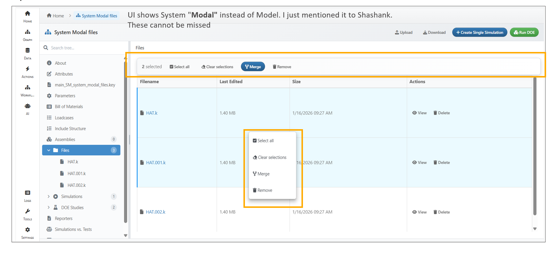
Files Actions
13.12. Tree View
System Models now display a tree view for tabs and a breadcrumb header for viewed files.
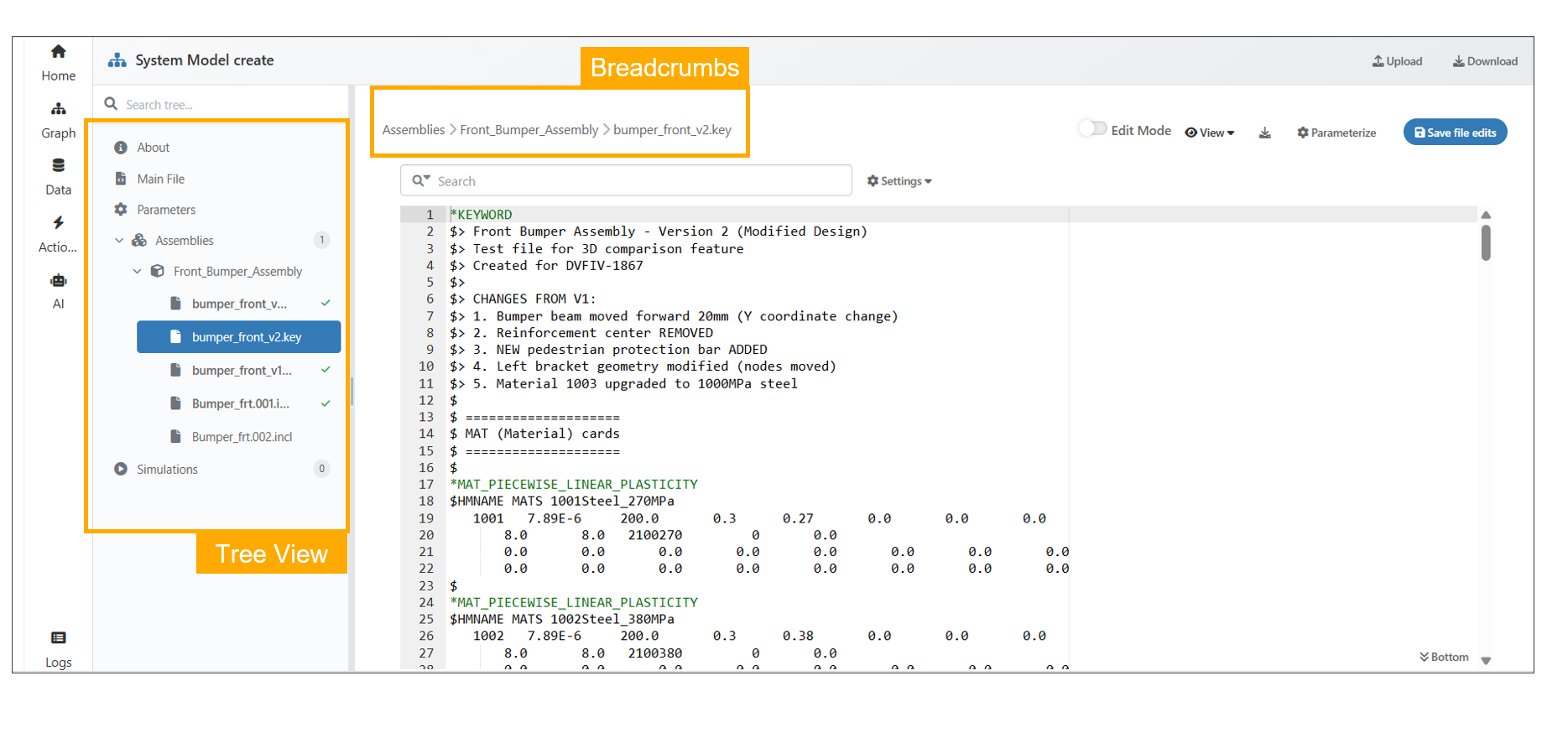
Files breadcrumb
The System Model ‘About -> Total Files’ option now shows file breadcrumbs with an info icon popover displaying size and last modified details, highlights the selected file in the left tree view, and expands remaining files.
In Model Assembler page, if a system model includes a design step, it will now appear next to “Created by” in the About tab.
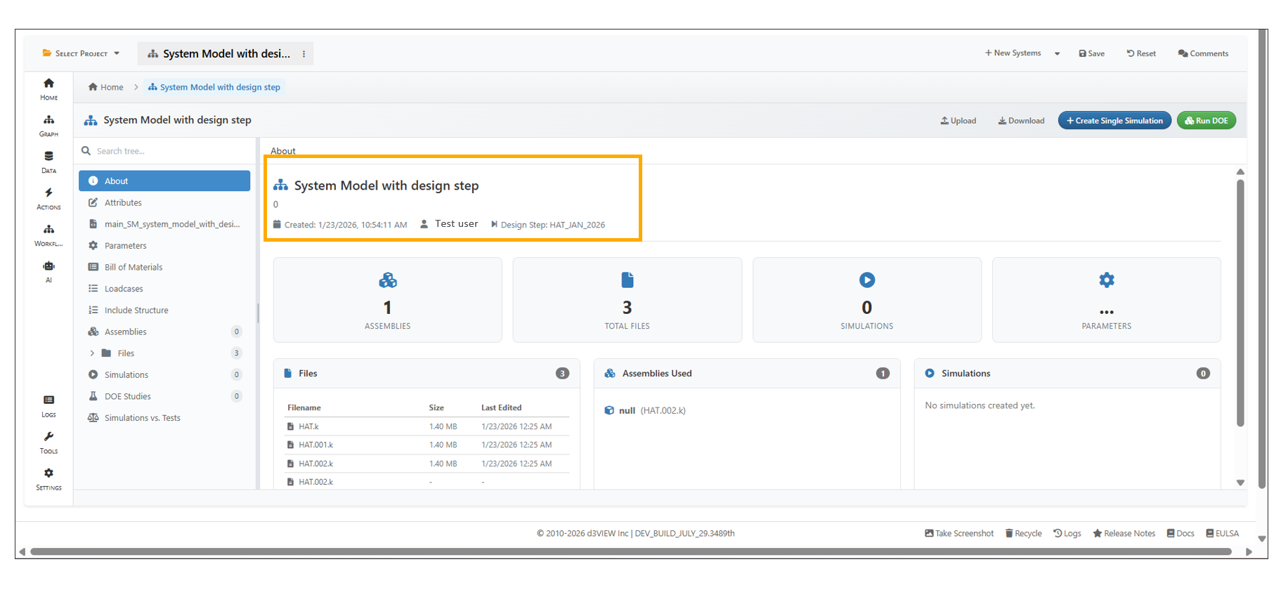
Design Step
Breadcrumbs are displayed in the header when a file is opened from the dashboard or a direct file under a System Model.
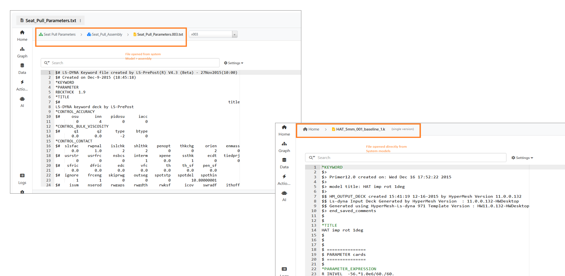
Files breadcrumbs
DOE studies in the System Model tree view now display a checkmark when their simulations have finished running.
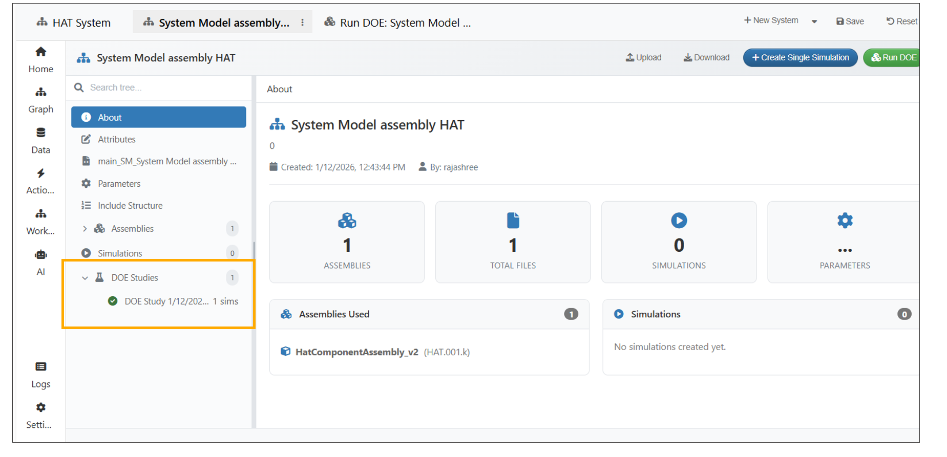
DOE Study checkmark
Under DOE Studies within a System Model, when a DOE study is selected, a grid view showing information about the study and the simulations associated with the selected study are displayed.
Attribute names in the System Model can now be edited and saved to the System Model.
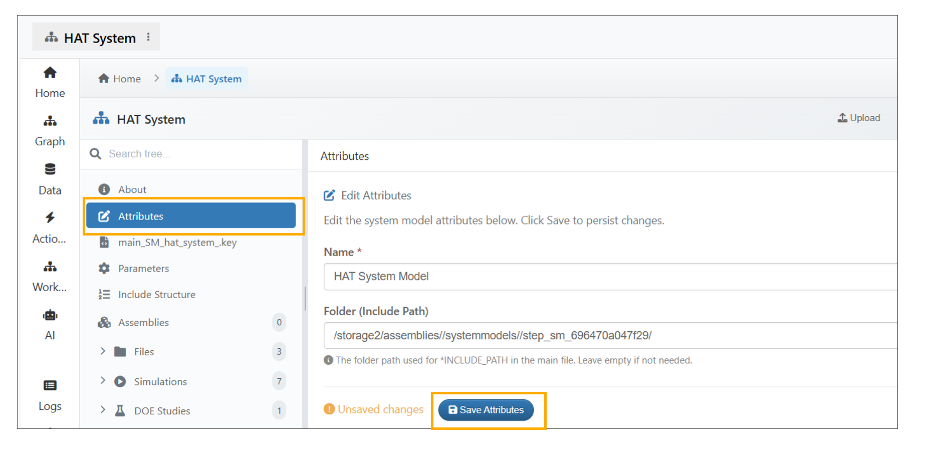
Attribute names
System Models now support viewing of Bill of Materials (BOM) directly from the left tree panel, with BOM data loaded and rendered in a tabular format.
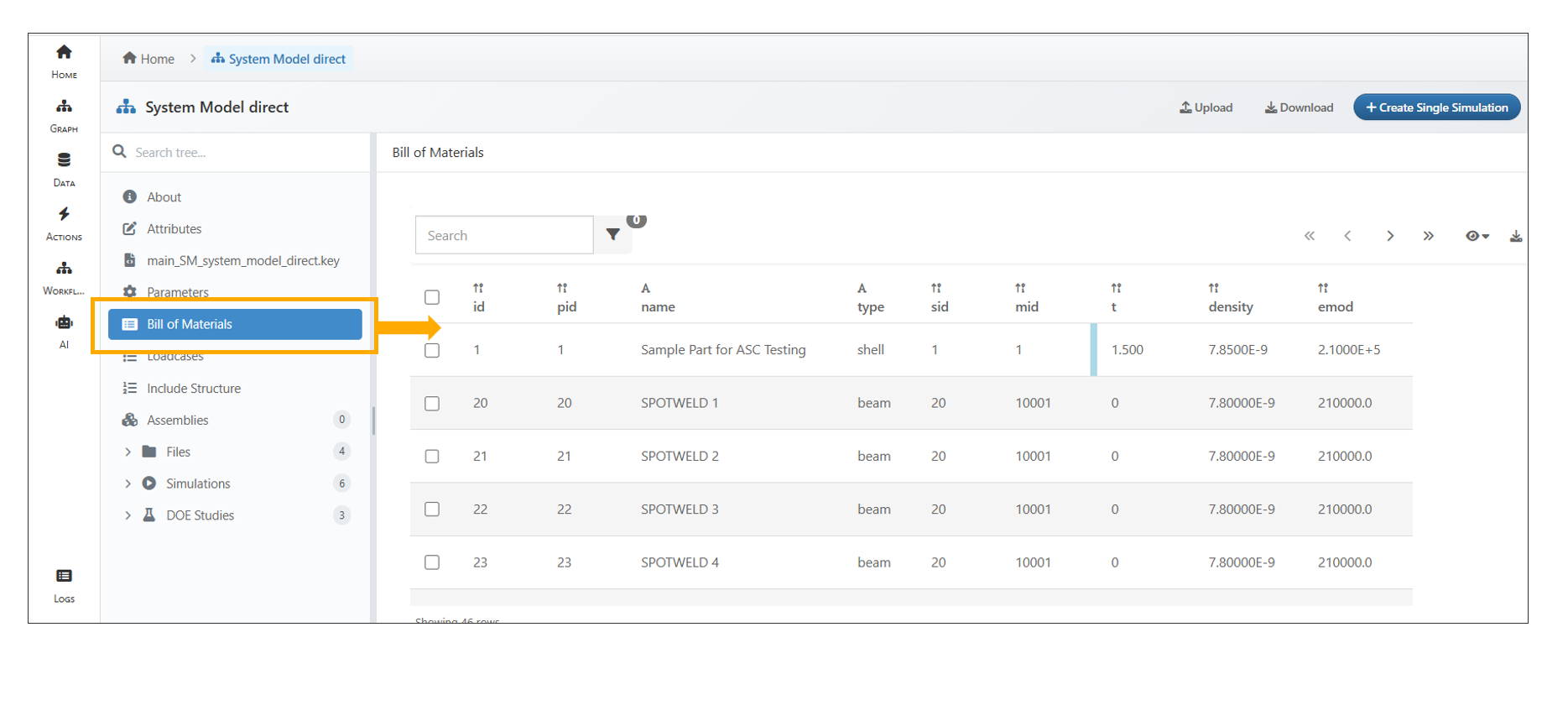
Bill of Materials
13.13. Include Structure
The System Model now includes a new Include Structure tab in the tree view, displaying the assemblies and files. Files can be opened by clicking the file name or the View button, and the header now shows a breadcrumb for easy navigation.
The Include Structure in System Models under Model Assemblers now supports a search bar in the header, allowing users to directly search for files and assemblies.
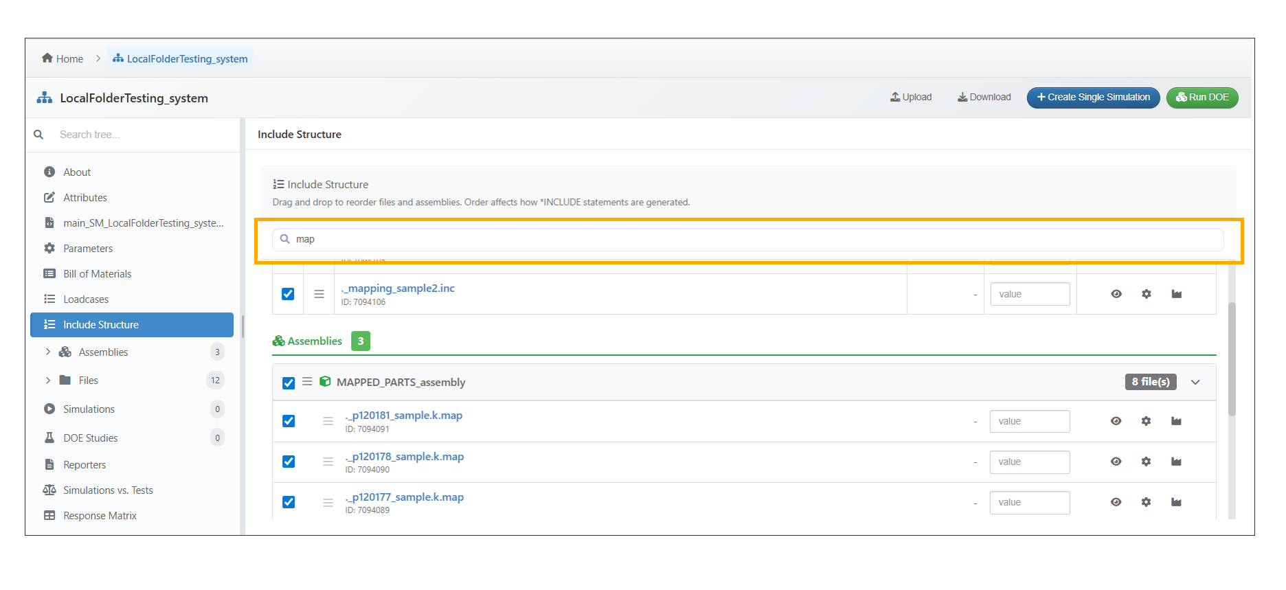
Search Bar
From the System Model’s Include Structure tab, users can open Stamped Part Settings for any file, configure and save stamped part parameters, and see the updated values reflected in the main input content.
Transform Configuration now pre-fills the Title with the filename, preserves transform operations and element offsets and generates DEFINE_TRANSFORMATION and INCLUDE_TRANSFORM statements in Main input file under System Model.
Files in the System Model’s Include Structure can be enabled or disabled using the checkboxes next to each file.
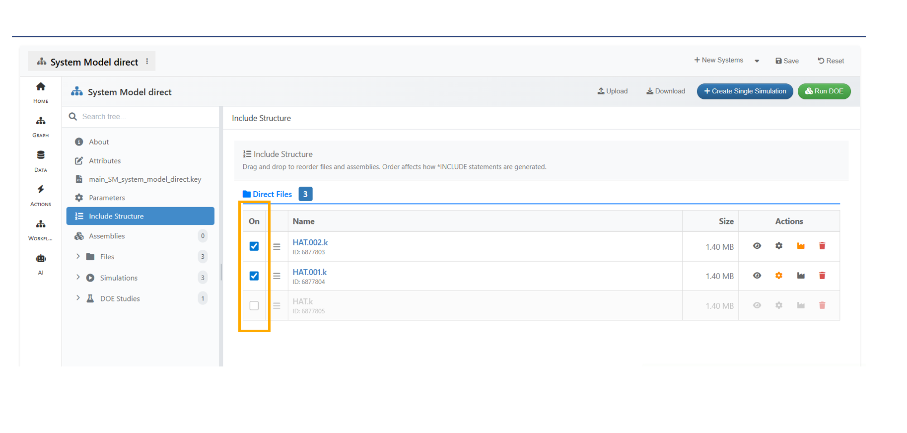
Enable or Disable files
In the System Model’s Include Structure, file ordering, enabling/disabling of files and transformations are carried over to the Loadcase Editor during simulation creation, and the Include Structure can be further modified in the Load Case step using the context menu option in the Template view.
In Model assemblers, the Modifications made to files in the Loadcase editor can be saved back to the System Model using the ‘Update Defaults’ option.
In System Model -> Include Structure, selecting file rows now displays a floating action bar and context menu with Select all, Clear selections and Toggle visibility options.
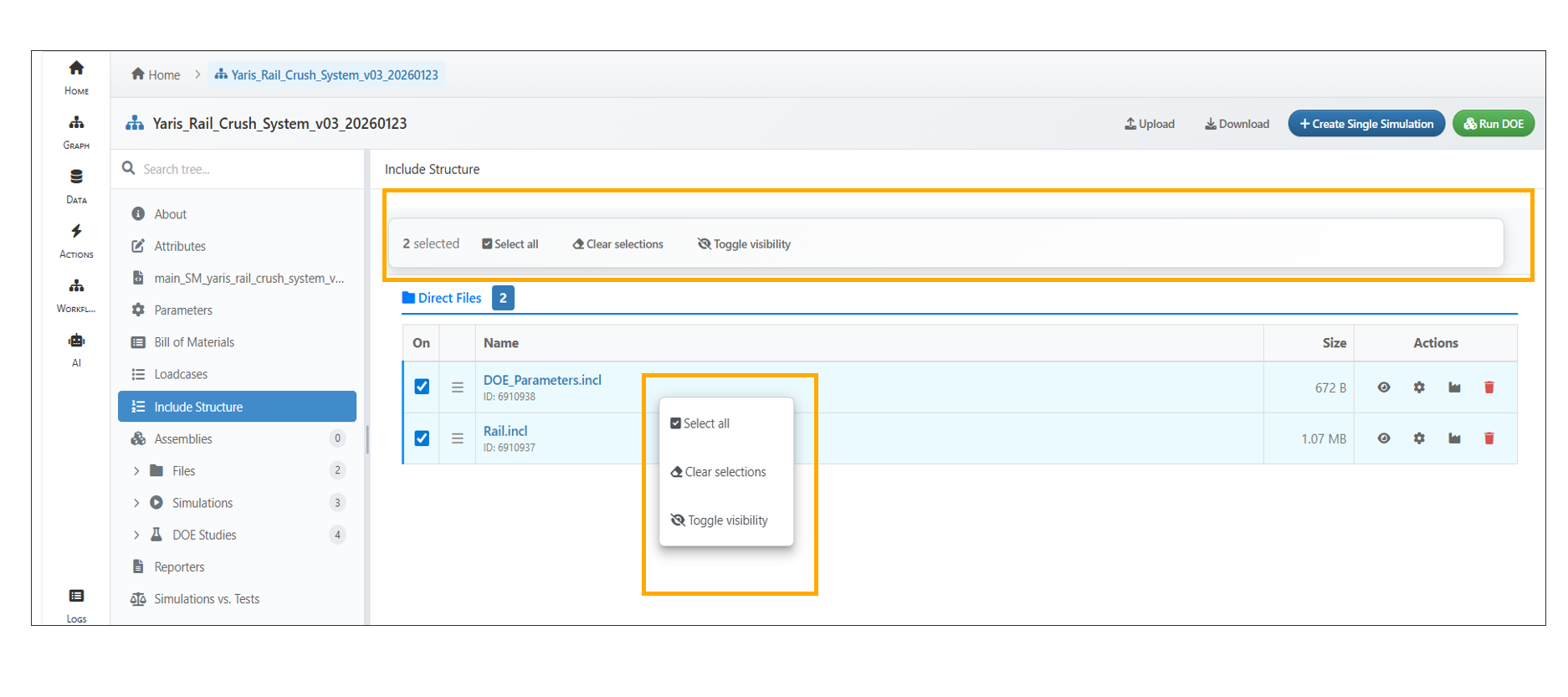
Floating actions
Model Assembler now supports C parameter for files in ‘Include Structure’ under System Model, allowing direct and assembly files to define, update, clear C params that become available in main input file while creating a simulation.
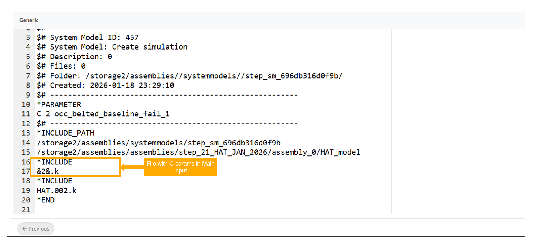
C Parameters
13.14. Response Matrix
A new ‘Response Matrix’ tab is now available in the system model’s tree view, displaying common responses across simulations along with an interactive table of remaining responses that updates based on simulation selection.
13.15. Simulations
Simulations can now be submitted directly from a System Model.
Assemblies associated with System Models are now displayed in the Custom Editor while creating a simulation.
In Model Assembler, while creating a simulation from a System Model, the Loadcase dropdown now shows source badges such as Proforma, Excel etc.
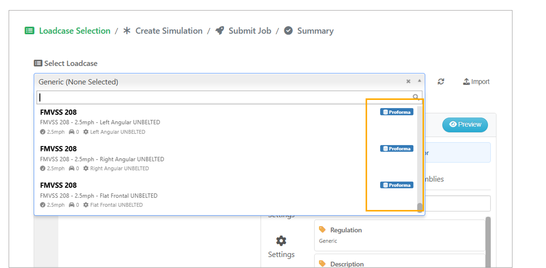
Loadcase
In the System Model → Load Cases editor, assemblies are now displayed as a single folder item in the sidebar.
‘Create Simulation’ now supports parsed and template views for load cases, saves manual edits in generated simulation files, and provides warnings for unsupported drag-and-drop actions.
Simulations in the System Model tree view now show two options: Open in Tab and Open in Modal. The Open in Tab option further includes an Open in Modal option in Model Assemblers.
In Model Assembler, the Loadcase ID input is now automatically pre-populated in Step 2 when a saved Loadcase is dragged into the editor during simulation creation.
Simulation creation from a System Model with assemblies now receives a CSV of assembly IDs, displays the IDs in the Configuration step, and includes an SM_INFO block with System Model details in the simulation description.
In Model Assembler, New → Simulation now opens a modal with two tabs: Tab 1 displays the simulation worker with System Model marked as a required field, and Tab 2 guides users through System Model selection first, followed by Loadcase selection.
13.16. Include path file attachments
In Model Assembler, Include File Attachment input options in System Model simulations now support configurable behavior with dynamic defaults based on the IncludePath setting during System Model creation.
13.17. Reporters layouts
Model Assembler now includes a Reporters tab that allows users to save and manage reporter layouts created by comparing simulations in Simlytiks.
Reporter Layouts saved in the Reporters tab can now be renamed, and their associated simulations can be modified to view the saved layouts.
13.18. Loadcase
Selecting a load case step during simulation submission now loads assemblies from the server with search and pagination support.
The System Model Edit Load Case sidebar is now simplified with a single Variables dropdown to switch between variables, these variables can be dragged to code editor and viewed as Parsed content using context menu.
In the Model Assembler, multiple loadcases can now be added with different configurations and simulations can be executed individually for each loadcase.
In Model Assembler, selecting multiple Loadcase rows for simulation now displays a floating header with options to Clear Selection, Remove Rows, and Add to Study.
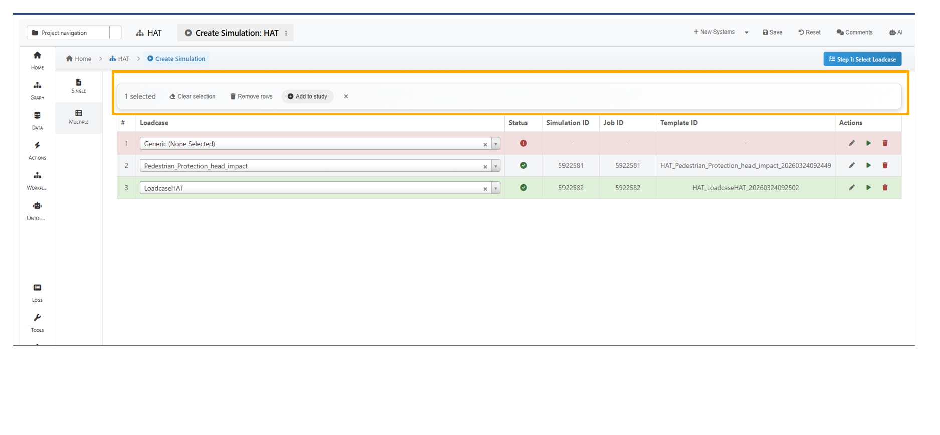
Header Options
The Loadcase Editor now displays saved loadcases in the Variables dropdown, containing LC_FOLDER and LC_FILES placeholders that can be dragged into the editor.
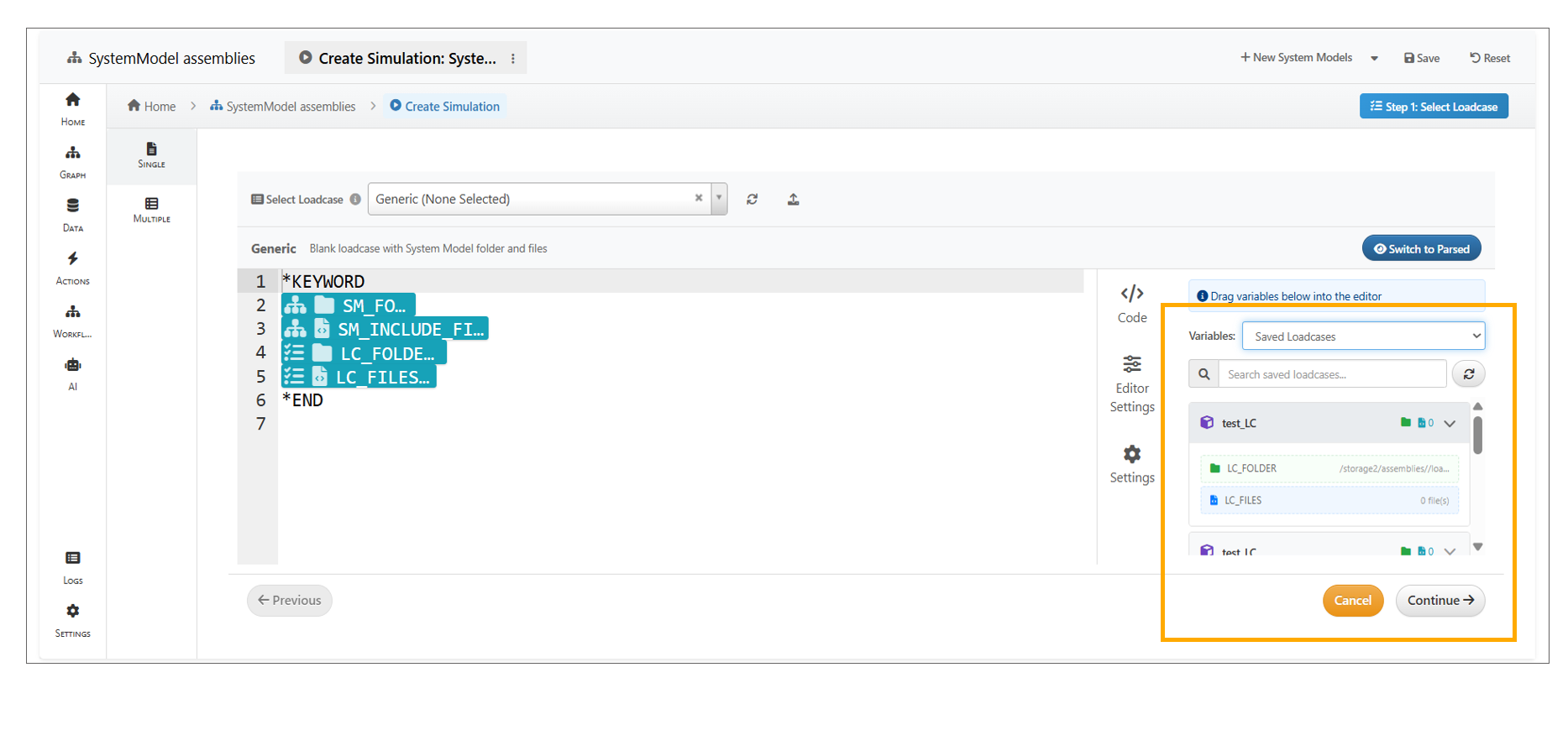
Saved Loadcases
While creating a simulation from an existing load case, LC_INFO in the Load case editor and the sidebar are pre-populated to show Loadcase Variables tab.
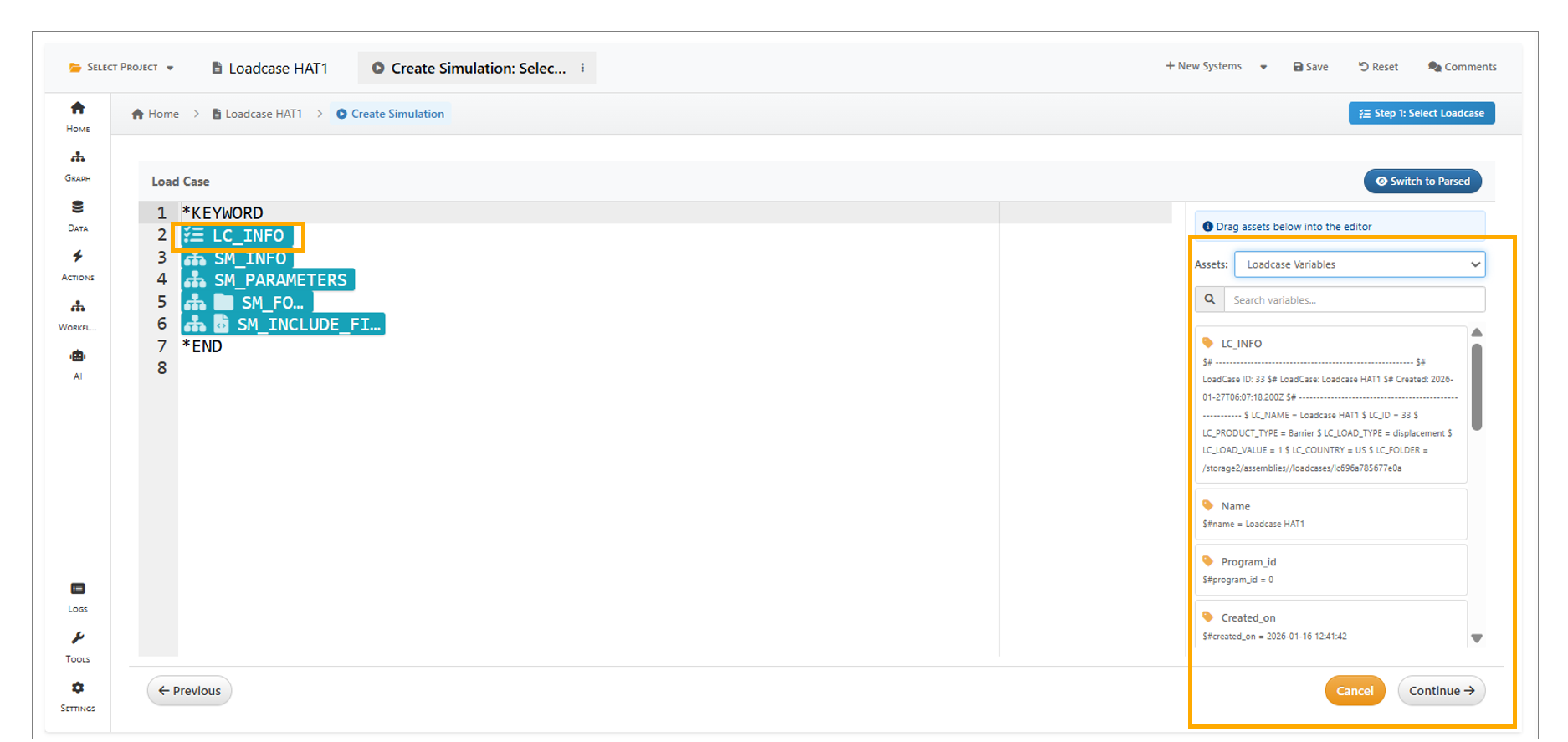
LC Info
In Model Assemblers, in Load Case Editor (Template mode), you can now modify the Include Structure of an assembly, enable or disable files, reorder them using drag-and-drop and ensure only enabled files appear in the selected order in Parsed View.
13.19. Import from files
Model Assembler -> Import From File wizard is added with multi-step flow for importing files into assemblies.
13.20. Import from Folder
Assemblers and System Models can be Imported from Folder using option available in ‘New’ button in the header.
13.21. Import from Remote Folder
Assemblers and System Models can be Imported from Remote Folder using option available in ‘New’ button in the header.
13.22. Transformations
A new Transformations option is now available for files in the System Model and Assemblies, with transformations saved to the files and can be verified in Loadcase editor step.
A Reset option is now available in the Transformations modal, allowing all values to be restored to their default settings.
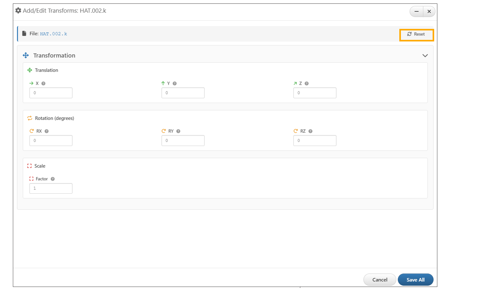
Reset Transformations
‘Transforms’ operation for the Assembly file now includes additional options in the Scale Factors section—Temperature Scale, Output Flag (dropdown), and Charge Scale.
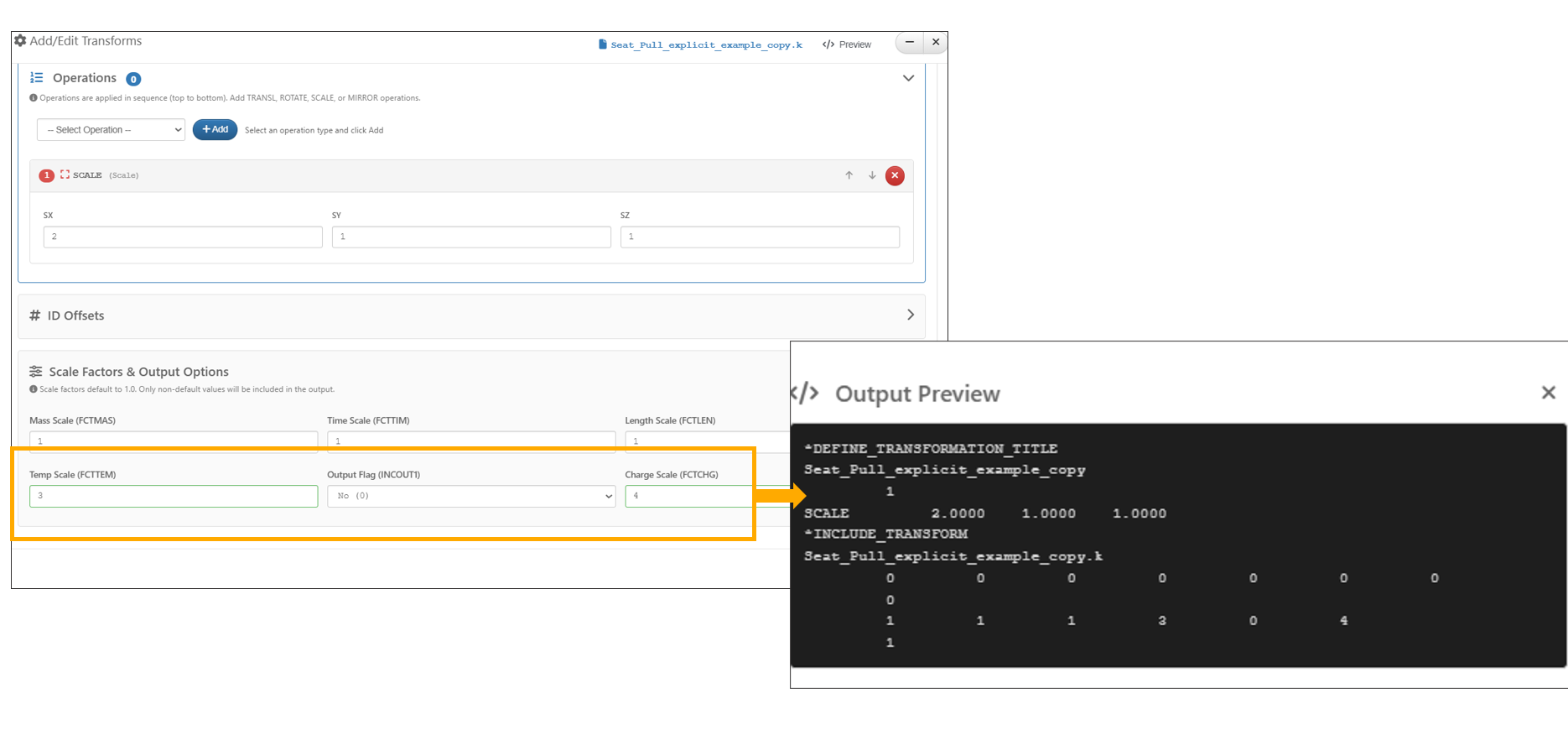
Reset Transformations scale factors
13.23. Physical tests
Model Assembler now includes a “Physical Test” option in the ‘+New Systems’ dropdown to create a Test, where creation tests can be done using ‘Basic’ tab with file or in ‘Advanced’ tab using workflow.
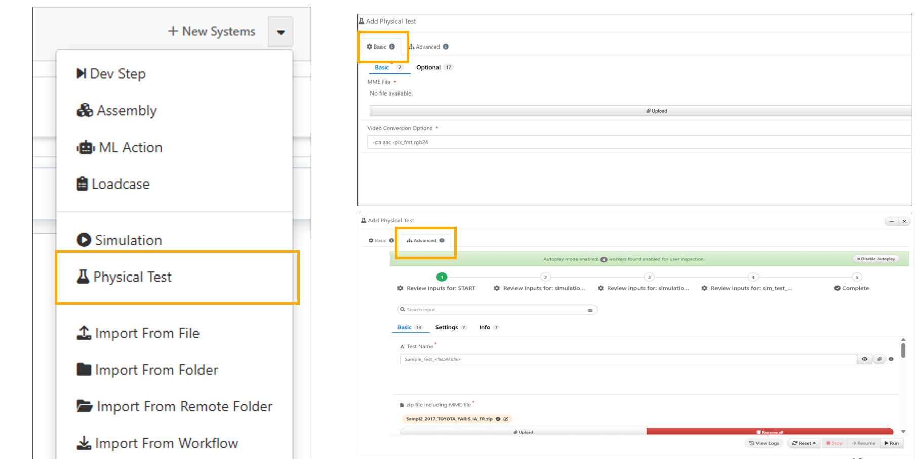
Physical test
Physical Tests can now be selected in Model Assembler settings under Dashboard Card Types and reviewed in the Home page header cards.
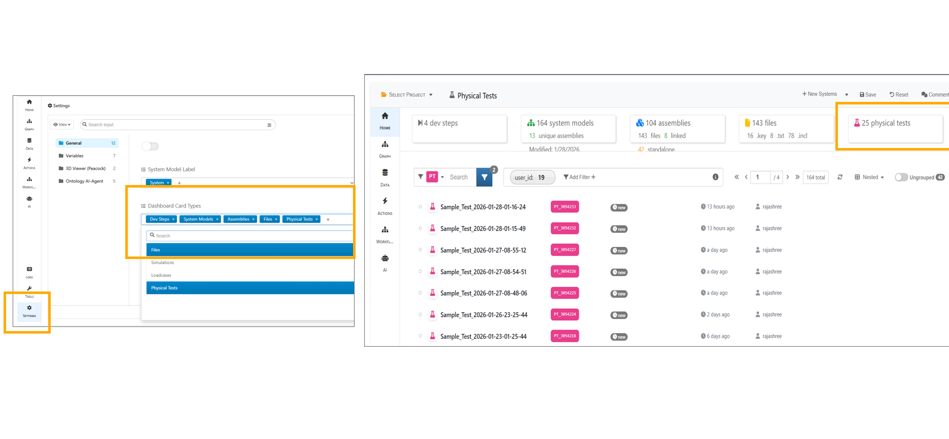
Physical test header Card
In Model Assembler, physical tests can be selected and compared in Simlytiks.
13.24. Databases
Model Assemblers now support databases and a new database can be created using the’ New Systems’ dropdown available in the header.
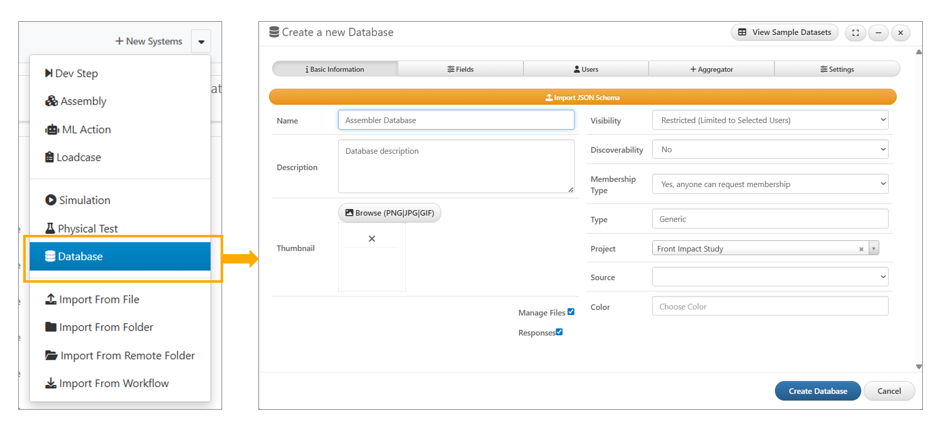
Database
Model Assemblers now support Databases which are available under ‘Dashboard Card Types’. The databases can be enabled or disabled by turning on or off the ‘Manage Materials’ option.
In Model Assembler, the total number of databases is now displayed within the header card for quick reference.
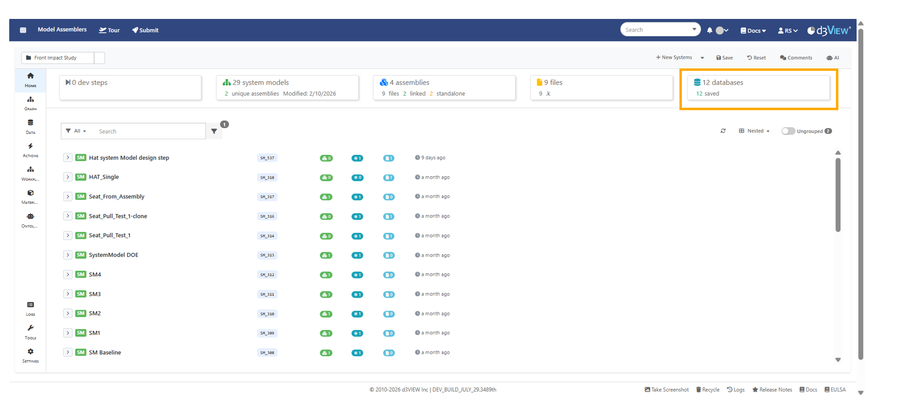
Database count
Databases can now be opened in Model Assemblers and includes ‘About’ page with database information, along with ‘Records’ and ‘Schema’ displayed in a left-side tree view.
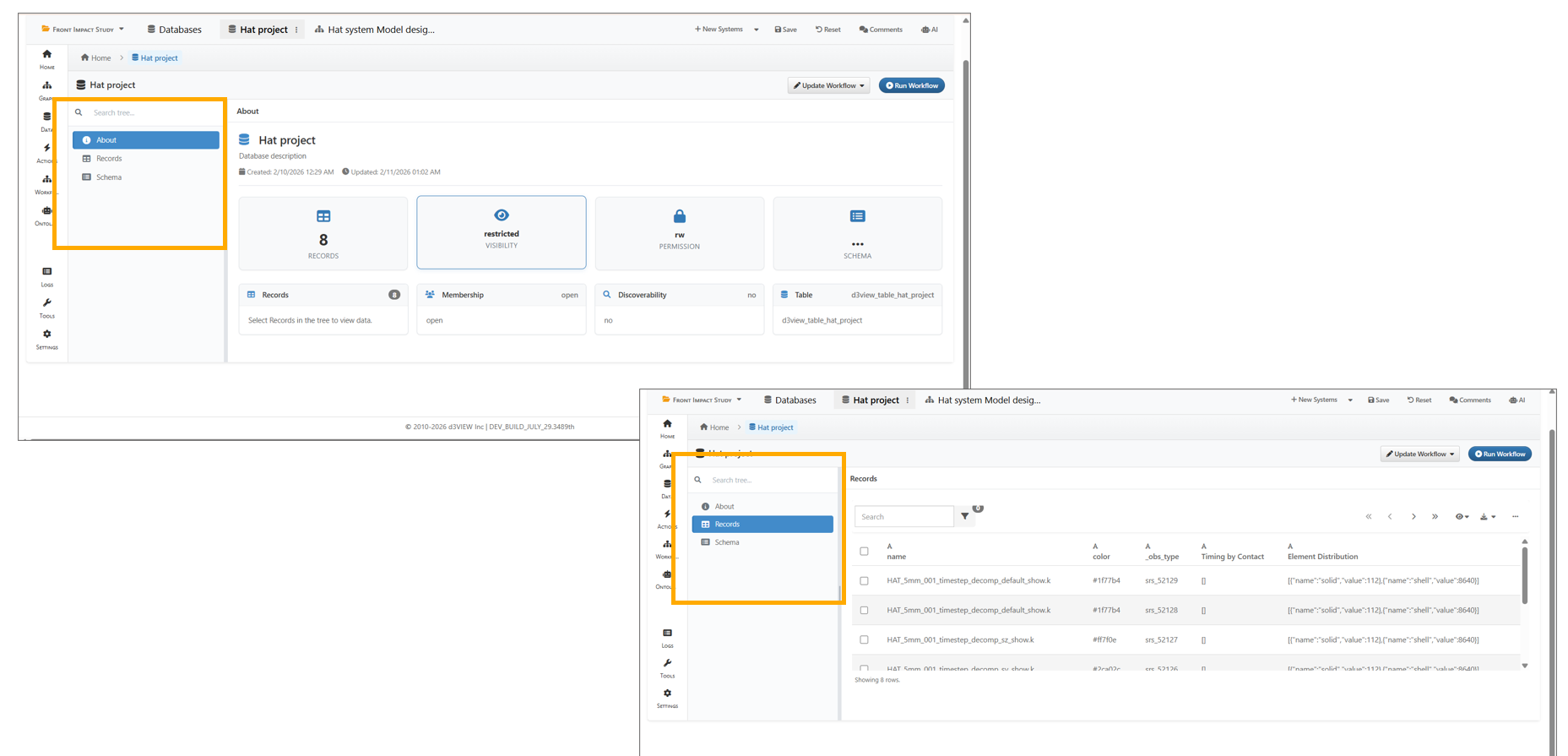
Database details
13.25. Run Workflow
In Model Assembler, when running Run Workflow From Database and opening Step 1, both Library dropdowns and My Workflows now filter results to display only workflows whose name or description contains Calibration, Calibrate, or Calibrator.
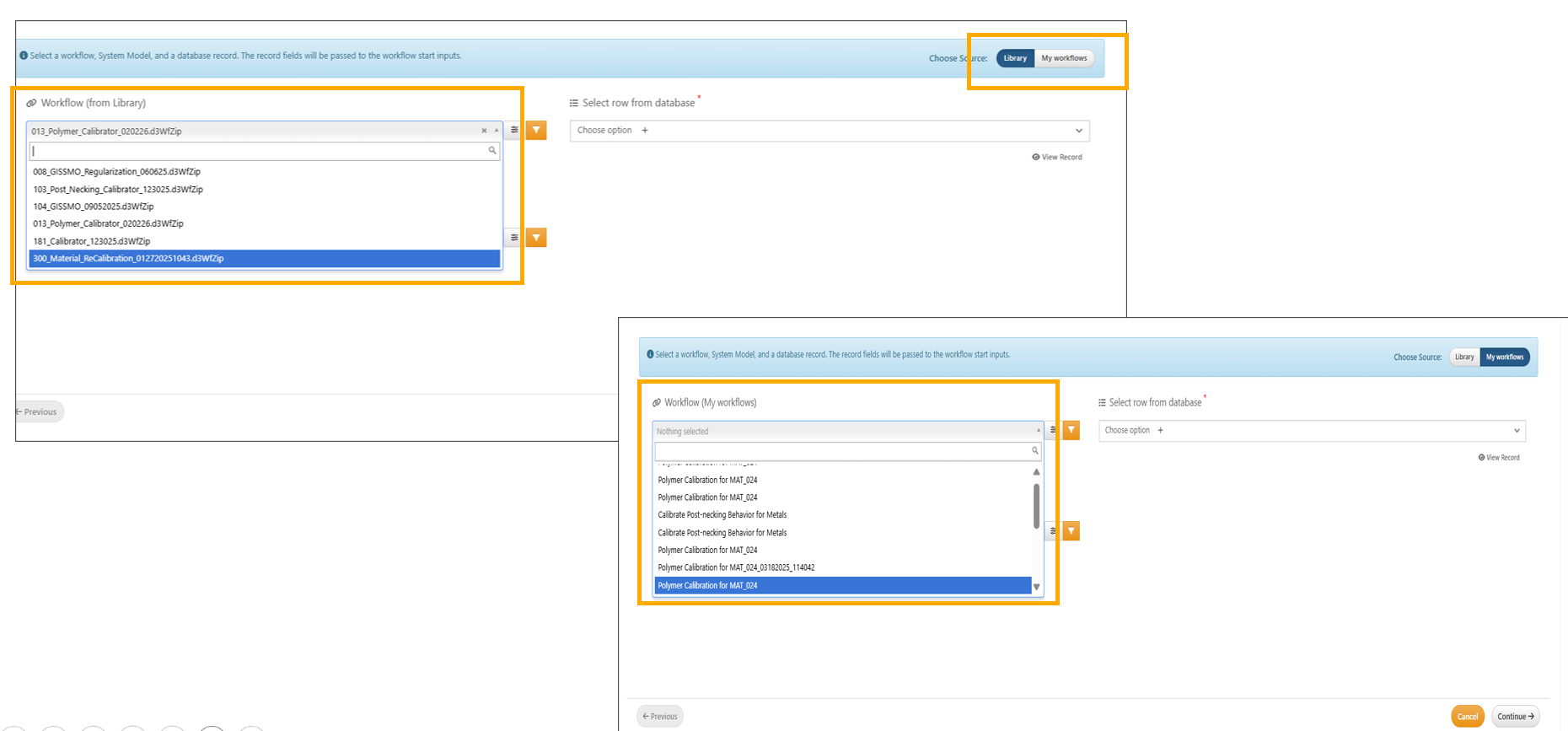
Run Workflow Step1
In the Database, when Run Workflow is opened, confirm that Step 1 displays the Library/My Workflow, the record input shows a View Record option when a record is selected and records values are shown in the sidebar.
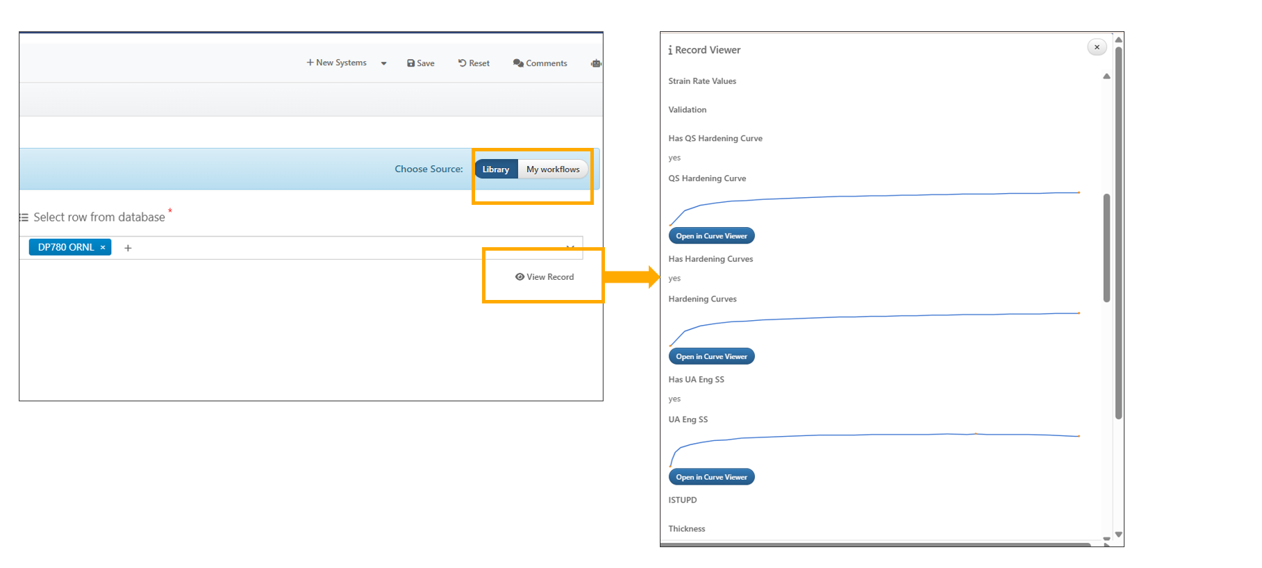
Run Workflow
In Model Assemblers’ database, users can now run workflows directly from a selected database and record, completing a three-step process: Step 1: select the workflow and records from the database; Step 2: map the inputs; Step 3: map the outputs. After completing these steps, clicking Continue will show the workflow with mapping and can be executed by the user.
13.26. Materials
In Model Assembler settings, when the Manage Materials option is enabled , the Materials tab on the left allows users to create a new material database to manage different materials.
In Model Assembler, user can delete or discard the Material created using the ‘Discard database’ button available in the Material tab.
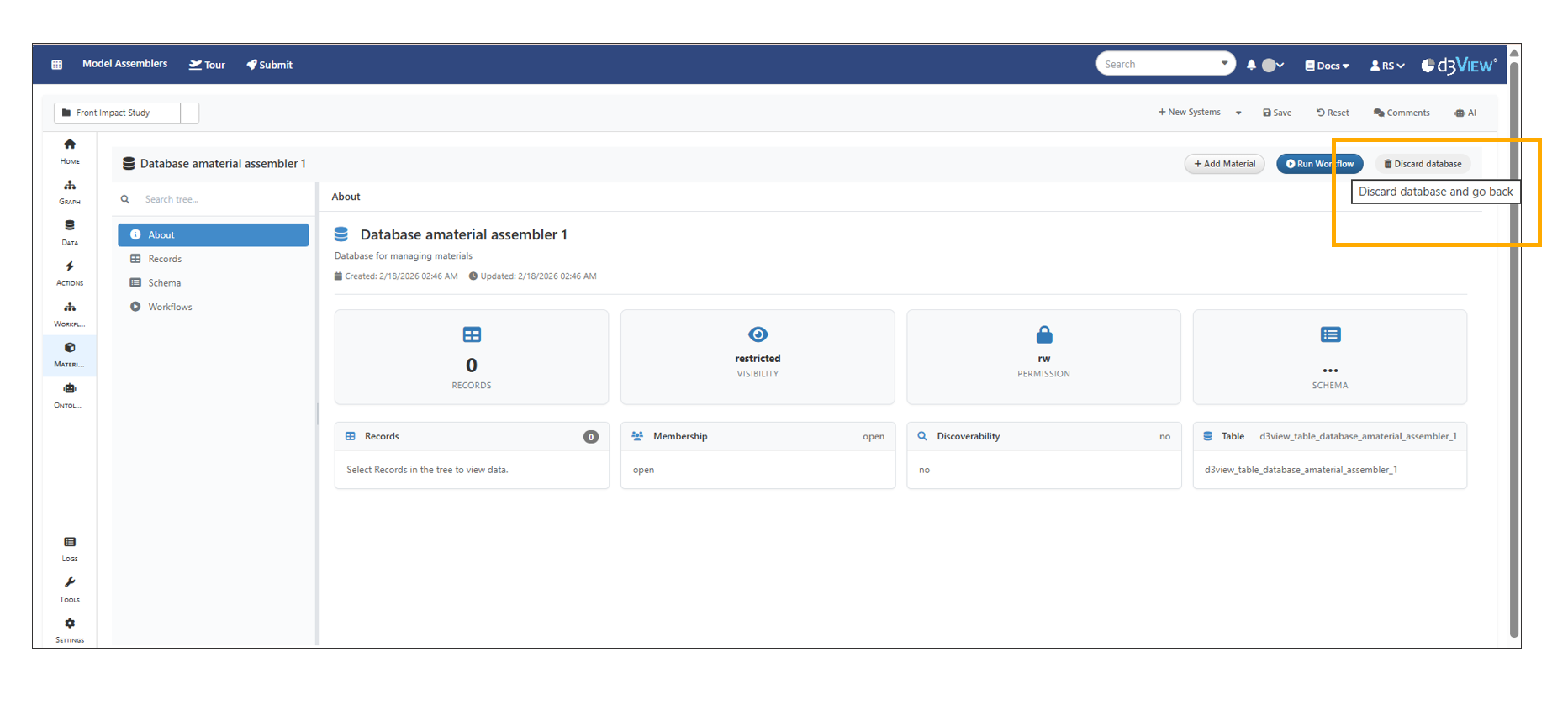
Database delete
The Materials tab now displays the latest materials schema with all non-required fields included, enabling immediate database creation with time stamp appended to the name of the material database to prevent duplicate failures.
Material Database “About” tab now dynamically updates the record count as users add new records.
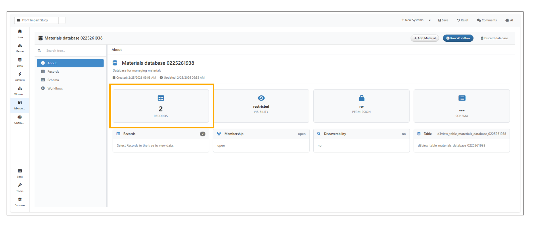
About
Running a workflow from the Material database now saves the “Run name” entered in Step 1 and displays it correctly in the Saved Workflows table.
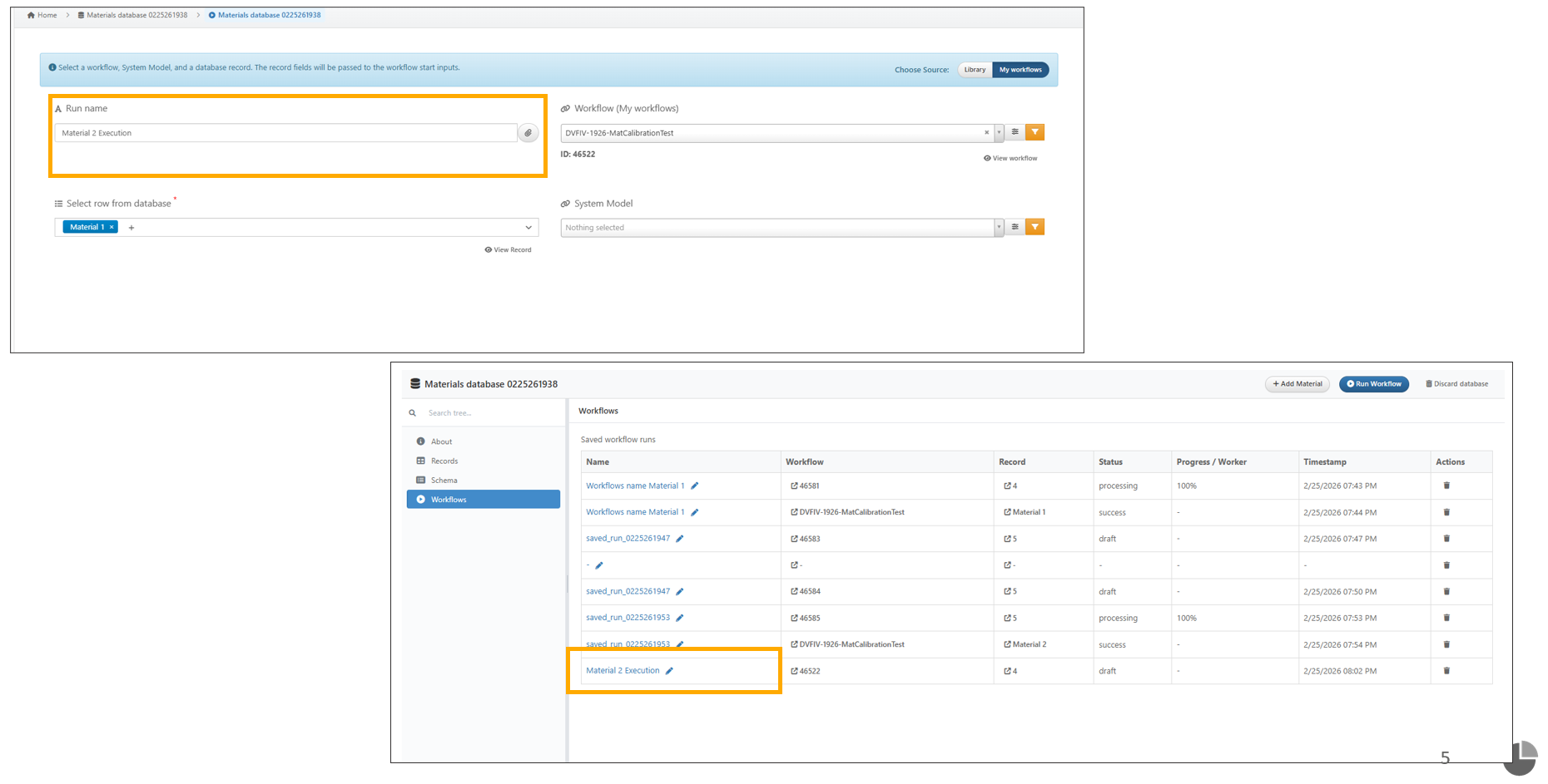
Run Name
Model Assembler settings now include a new “Use AI for Mapping Inputs” option that automatically maps inputs when running a workflow from records.
Input Mapping in Run Workflow now displays database record values on the right, includes an All/Mapped/Unmapped filter, and shows icons for each column.
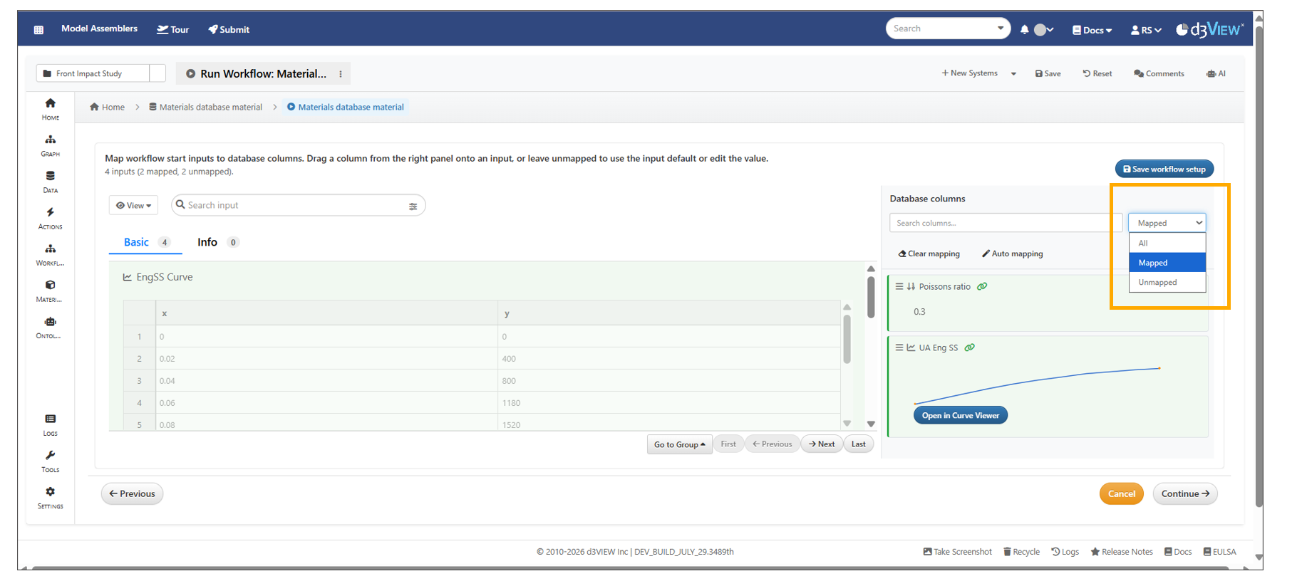
Inputs Mapping
13.27. Saved Workflows
Saved workflows from the Material Database on the Model Assemblers page can now be compared side by side either within the Material Database -> Workflows page or in Simlytiks using header options.
In Model Assembler’s Material Database, when using Run Workflow from Records, the workflow is initially saved as a draft and is updated automatically after the workflow is executed.
In Model Assemblers, saved workflows in the Material Database can now be compared in Simlytiks for all outputs or only the outputs selected by the user.
In Model Assemblers, saved workflows in the material database can now be removed using the delete icon available under right-side actions.
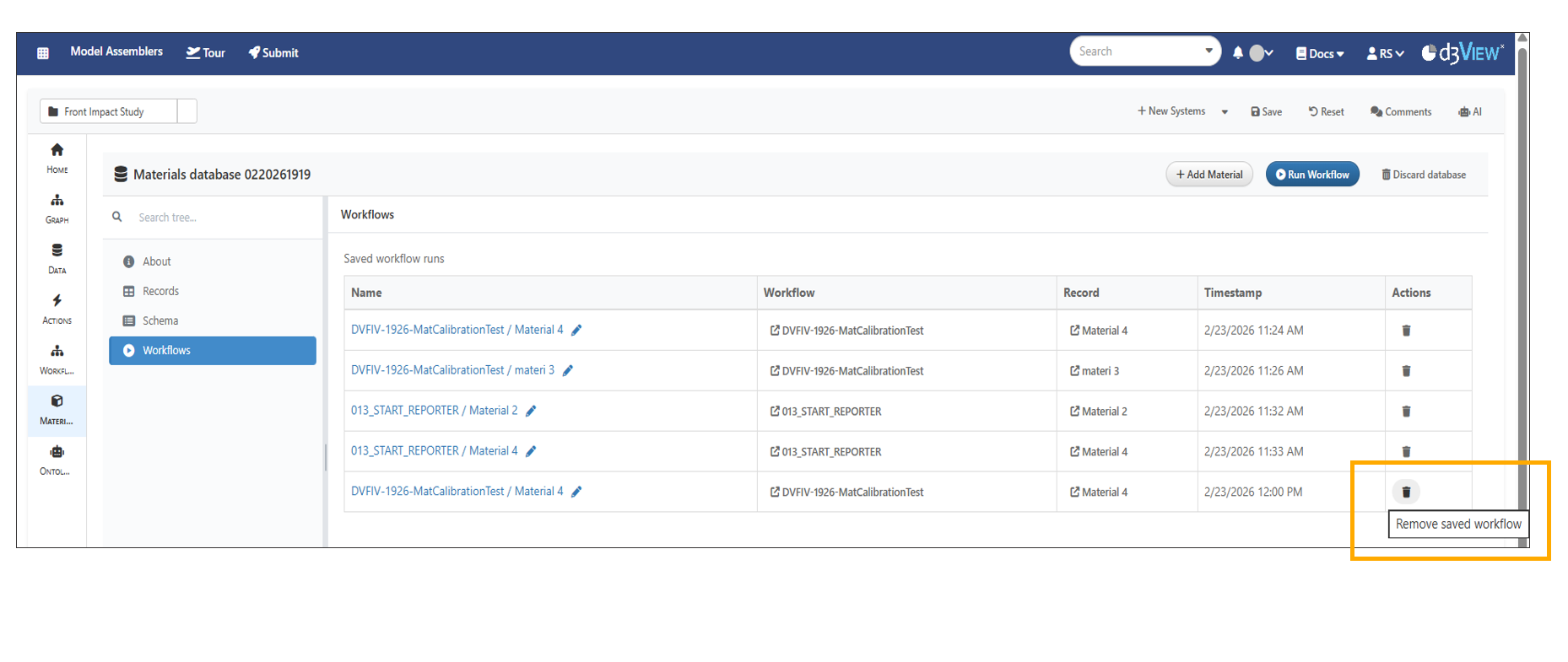
Delete Saved Workflows
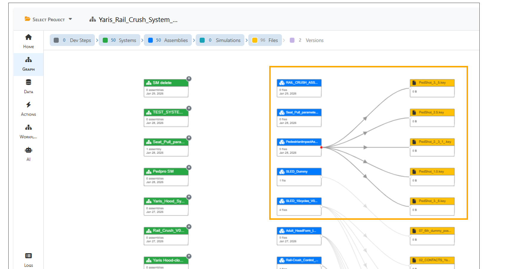
13.28. Graph
The Graph tab below Home visualizes the connections between Models, Assemblies, Simulations and Files.
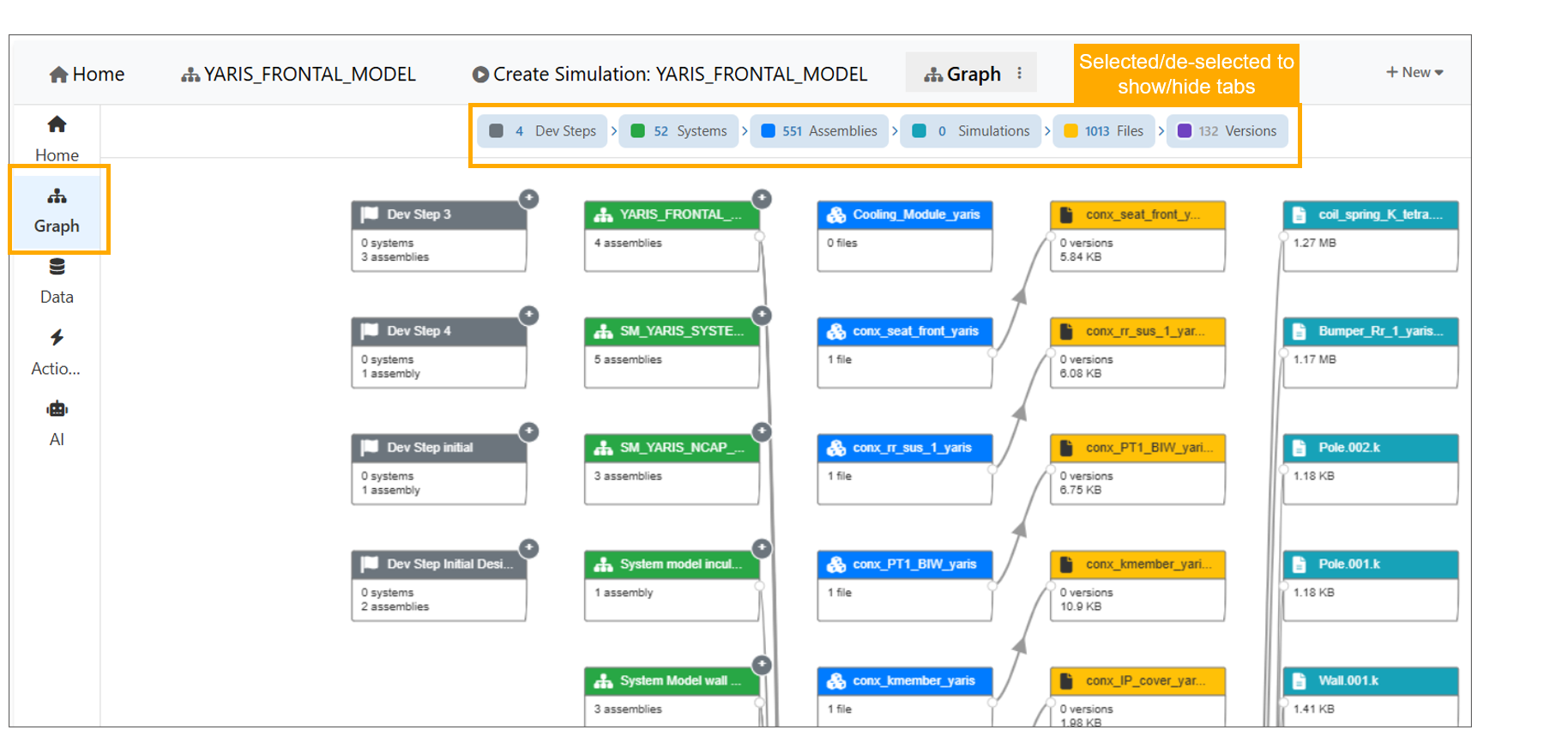
Graph
Context menu options are now available for nodes in the Graph tab.
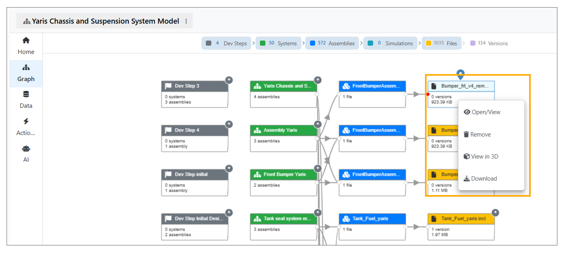
Graph Context menu
In Model Assembler, new view called ‘TimeLine View’ is available in Graph tab where System Model nodes display a thumbnail image in the body section.
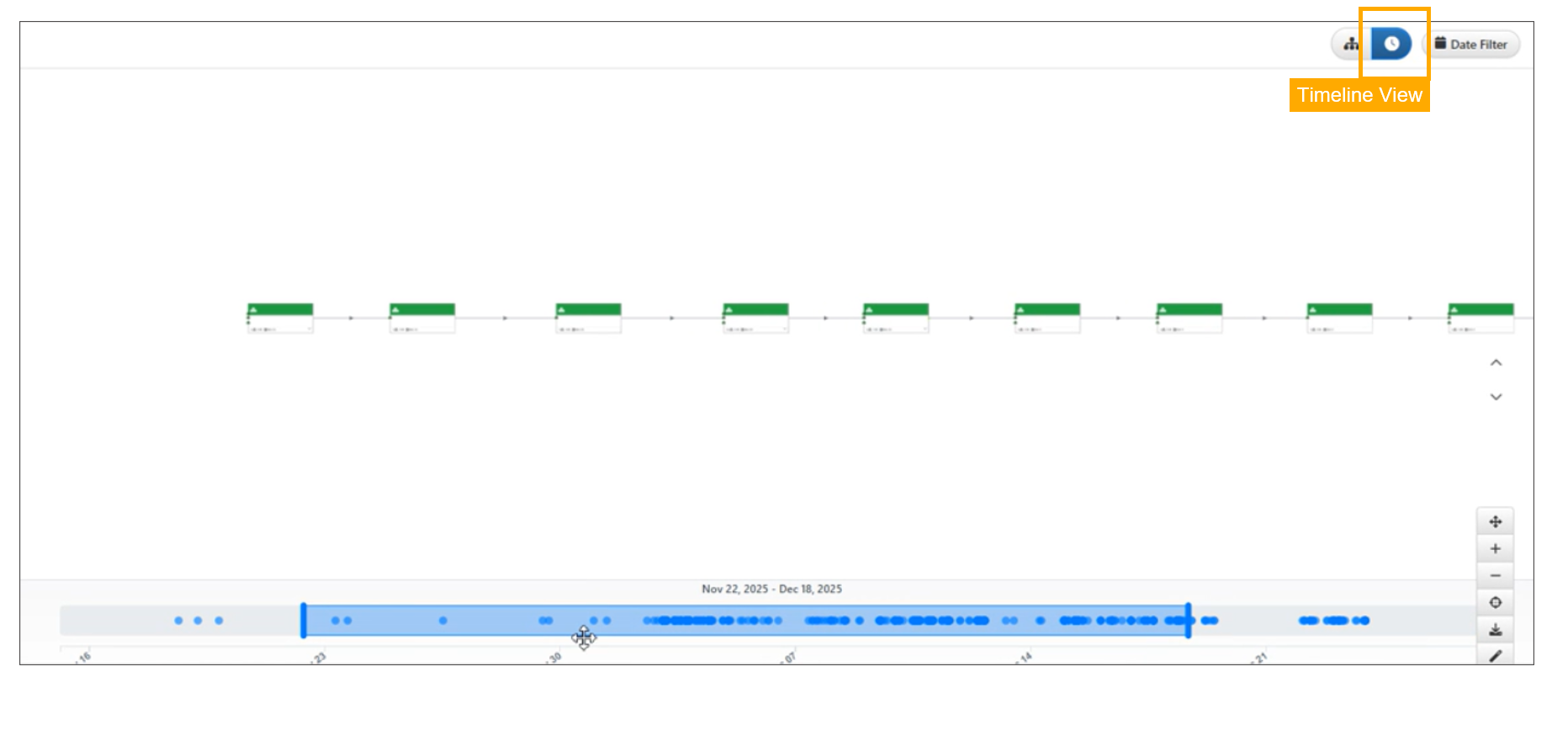
Graph Timeline View
In the Model Assembler graph, hovering over a system or assembly now highlights only its connections, with increased spacing between the Systems and Assemblies.
Graph Timeline Hover
13.29. Data
The Data tab below the Graph displays all records from Design Steps, Models, Assemblies, Files, and Simulations, with clickable labels to open them.
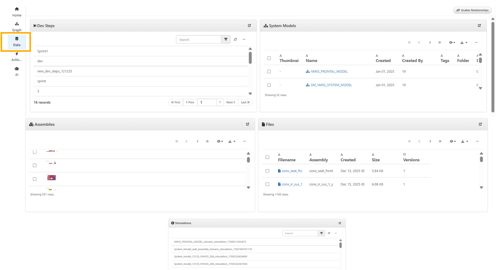
Data tab
In Model Assemblers page, the Data tab has button to ‘Show Relationships’ to view the relationship schema. User can switch back by clicking Hide Relationships.
The ER diagram under the Data tab has been updated to display relationships when hovering over tables in the Model Assembler.
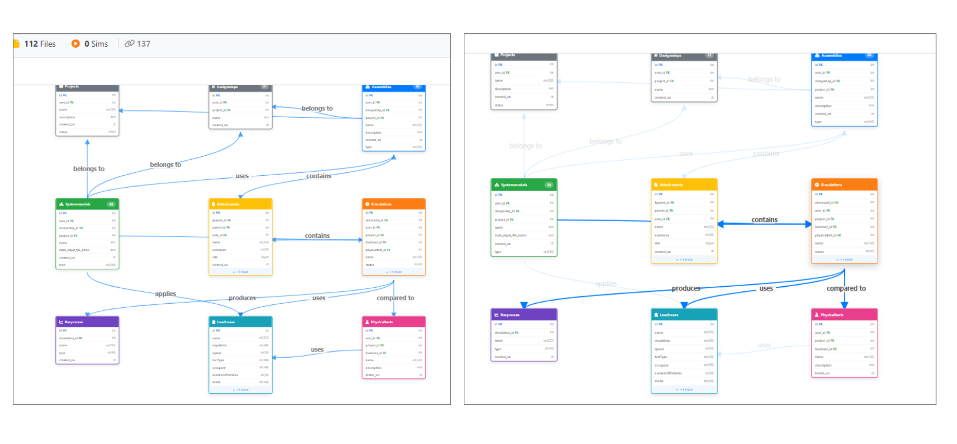
ER diagram
Model Assembler Data View now includes a new Physical Tests panel displayed after the Loadcases panel. Users can select the View action on a physical test item to open and review its detailed information.
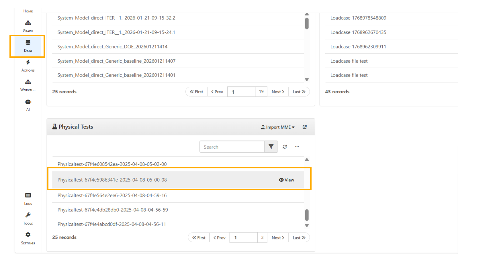
Physical Tests
13.31. Workflows
Model Assembler now includes a new Workflow tab in the left panel, displaying existing assemblies as completed assembly workers and existing System Models as completed system model workers.
13.32. AI Agent Ontology
Model Assembler AI now renders without wizard steps. The configuration dropdown toolbar settings can be used to configure and build graph per configuration.
The AI Ontology Workflow tab in the Model Assembler now includes a Settings tab in the right-side header, allowing configuration of settings and rebuilding the graph using the Build Graph button.
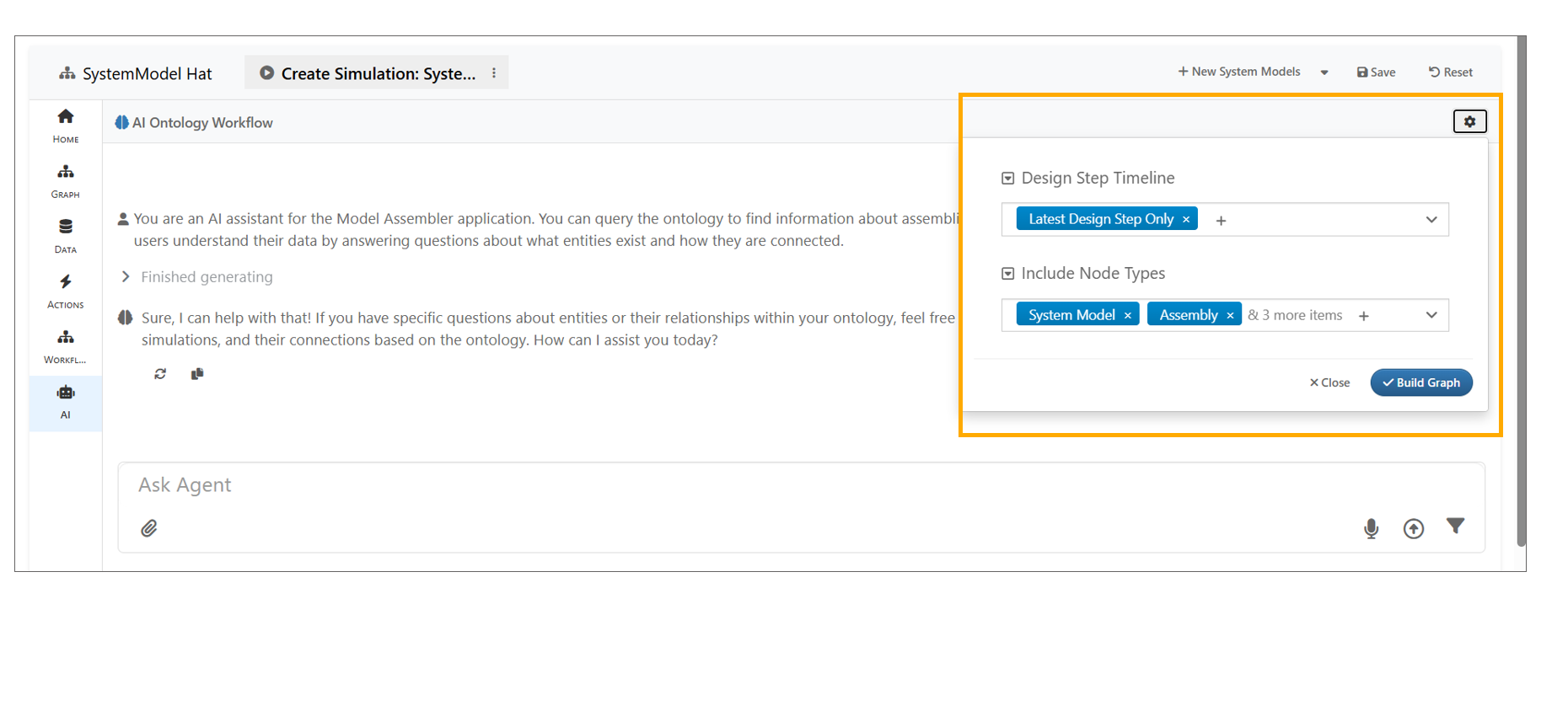
AI Ontology Workflow
13.33. Conversation Management
Overview
The Ontology Agent in Assembler now supports saving conversations to projects and switching between them. This improves context management, making it easier to maintain coherent dialogue across multiple sessions or topics.
Key Features
- Save Conversations to a Project - Store the current conversation thread under a specific project. - Facilitates reference to past interactions without re-entering context.
- Switch Between Saved Conversations - Seamlessly load any saved conversation within a project. - Manage multiple conversation threads simultaneously without losing context.
- Improved Context Management - Maintains topic-specific memory for more coherent responses. - Reduces redundancy and improves workflow efficiency.
13.34. Settings
A new Settings tab is now available in Assemblers.
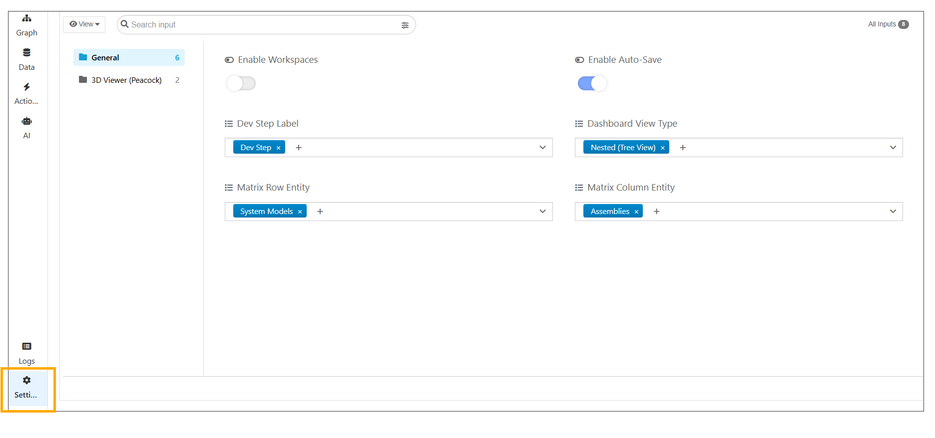
Settings
The Dev Step label can now be changed in ModelAssembler Settings, and all the Dev Step labels are replaced with the selected name across the application.
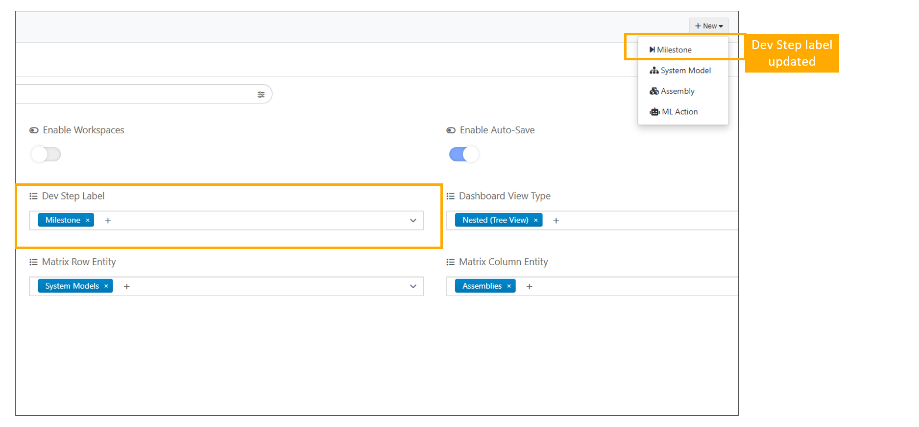
Dev Step label
Introduced Workspace support in Model Assembler under settings to organize and filter assemblies, system models, and design steps by project.
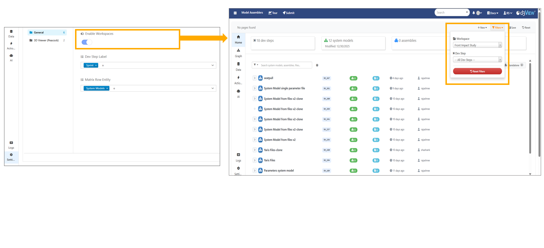
Workspace
New setting is available to Show Simulation Sidebar filter that renders the Simulation Home Page tab in the home page sidebar.
The Model Assembler page now includes a new ‘Allow File Versions’ setting, which is disabled by default to prevent files from updating to newer versions.
13.35. Active Workspace
Active Workspace dropdown is now available under settings in Model Assembler. The selected workspace automatically fills the project_id when creating assemblies, system models, or design steps.
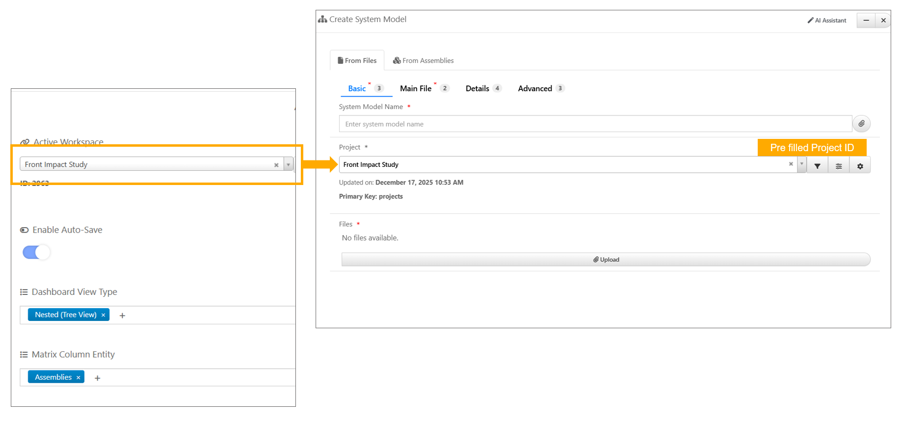
Active Workspace
13.36. Variables
In Model Assembler Settings, users can now customize the Simulation Name Pattern under settings. The custom pattern (e.g., TestSim_<%LC_NAME%>_<%DATE%>) is applied when creating new simulations.
13.37. Filters
In Model Assembler, the Filters dropdown has Dev Step filter for filtering of records.
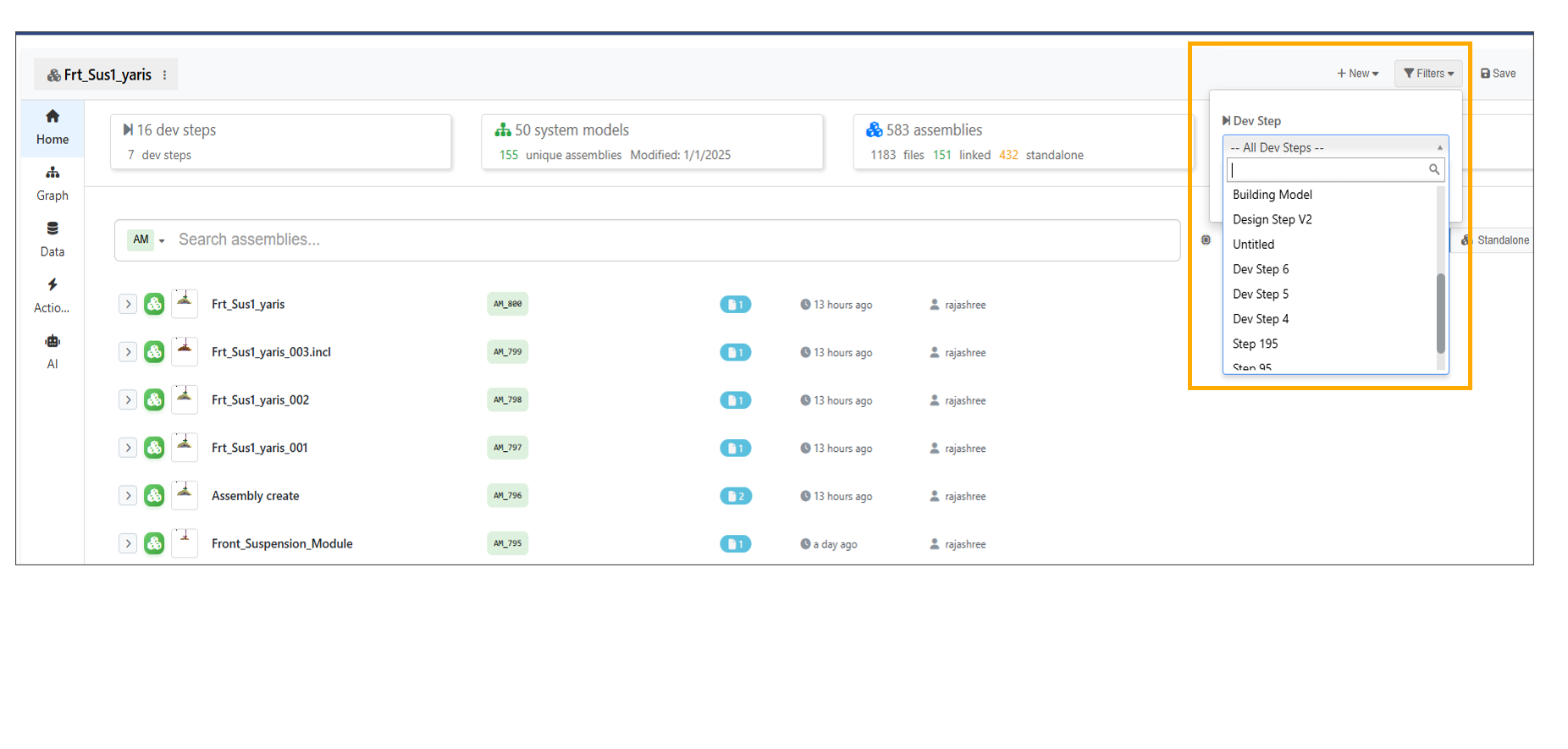
Filters
System Models with Simulations filter is now available, showing only system models that contain simulations on the page.
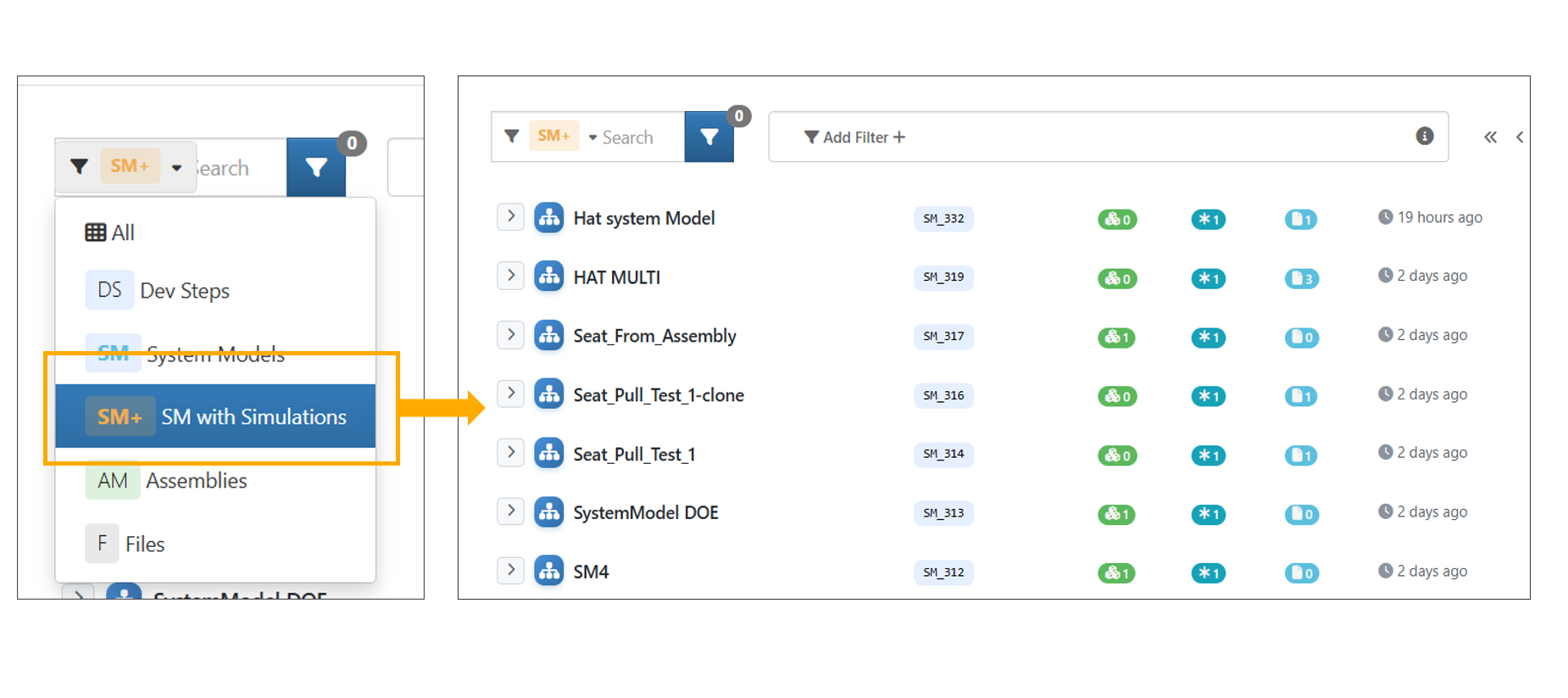
SM with Simulations
In Model Assembler, applied filters (such as project or user filters) are now retained when changing the search type, restored on page refresh with correctly filtered data and consistently applied across System models , Assemblies and Dev Steps menu options.
Filters are available on the Model Assemblers page, allowing users to filter records by Workspace or Project ID.
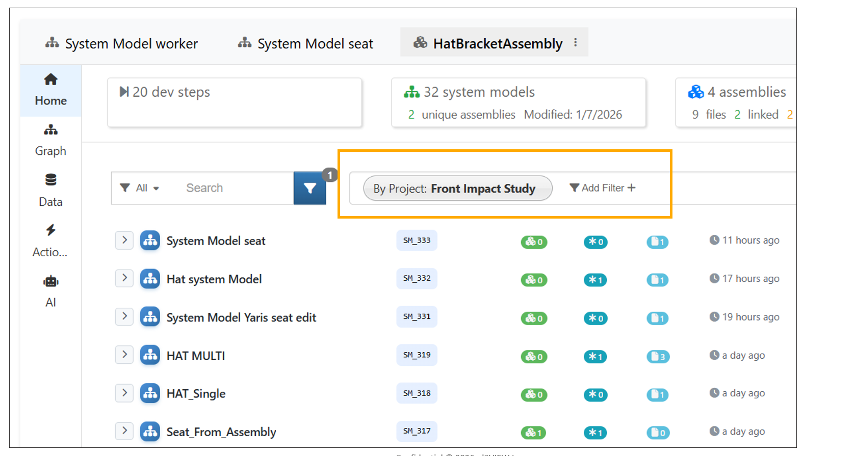
Add Filters
Model Assembler dashboard now preserves selected filters even while switching between different pages and views.
13.38. Dev Step
Opening a Dev Step in Model Assembler now displays a three-column circle chart with (Assembly, System Model, and Simulation).
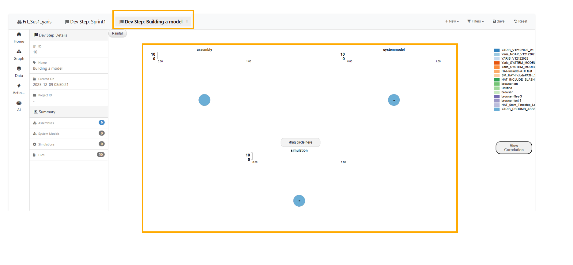
Three column circle
13.39. Selections
The selection bulk action bar is now positioned above the search bar on the Model Assemblers page.
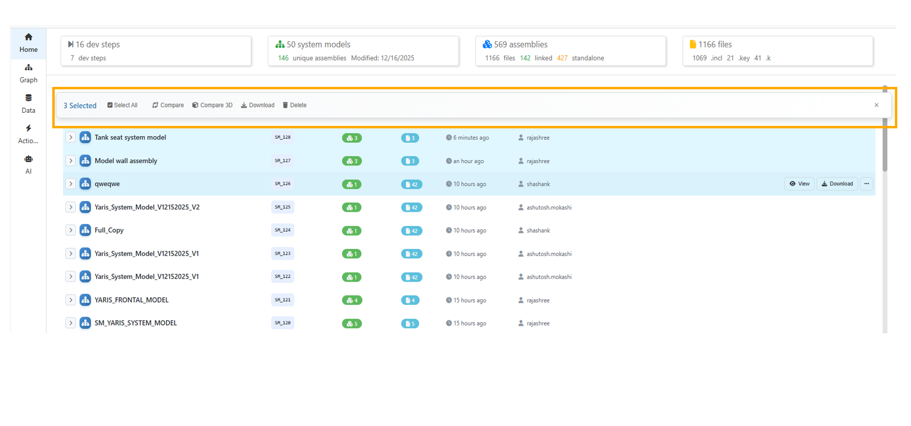
Selection bulk action bar
13.40. Comparison
Model Assembler: The comparison matrix UI is enhanced with a compact two-line layout. First row displays the file icon, filename, and inline status label. Second row shows category pills (S, G, M, B, O) along with a details link. A legend header is added above the comparison table for better clarity.
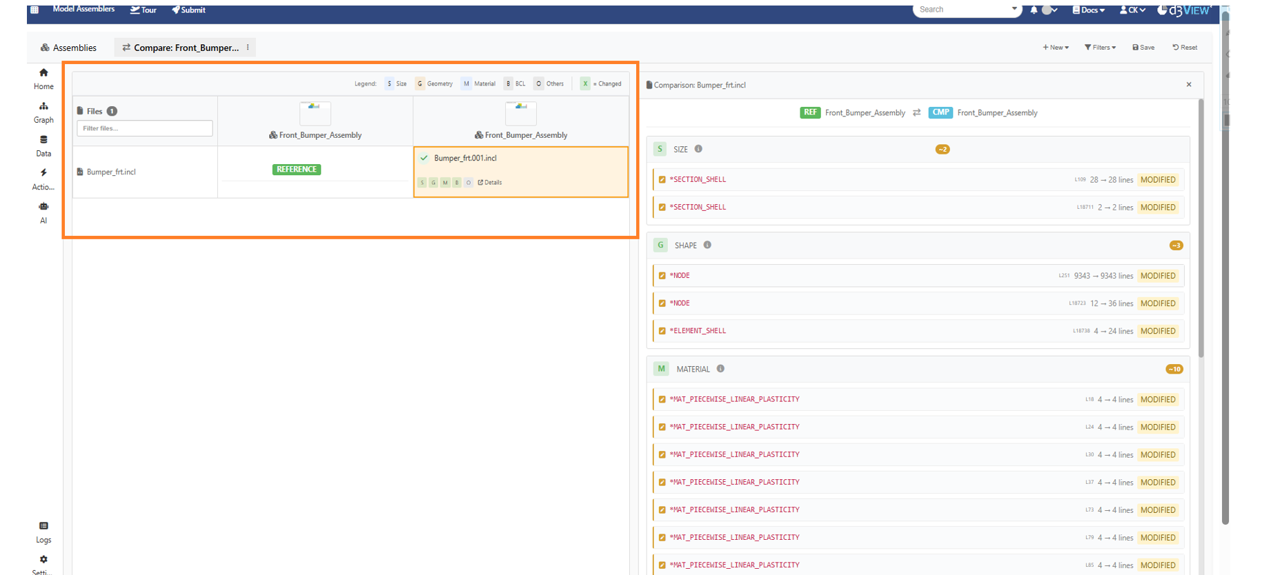
Model assemblers Comparison
Text Difference with two files will show line numbers in the center column between both editors.
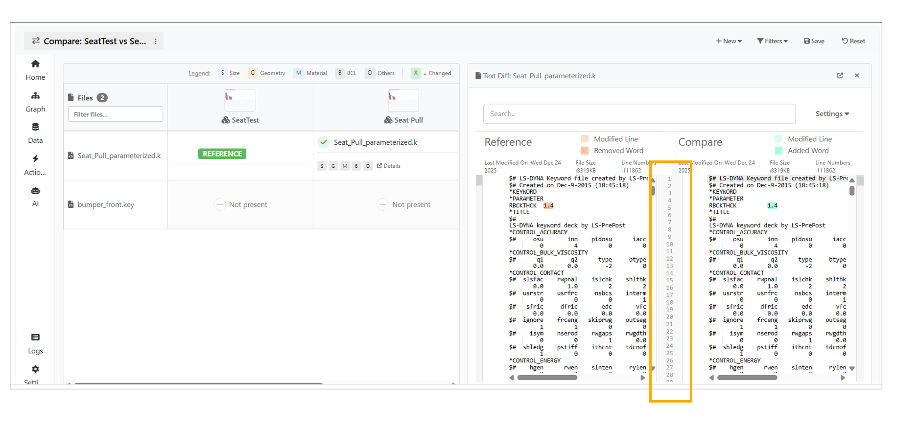
Text Difference
13.41. Comparison of Simulations
Simulations from System Models can now be compared in Simlytiks using context menu options.
Compare Simulations now opens in a new tab from the Model Assembler Dashboard, with Home breadcrumbs and footer actions, and supports launching Simlytiks in an overlay with back navigation and tab close support
13.42. Comparison of Simulation with a Tests
System Model now includes a new tab to compare simulations and physical tests side by side in tree view.
13.43. Ancestry tree
The Ancestry tree is now available under Options for Assemblies on the Model Assemblers page.
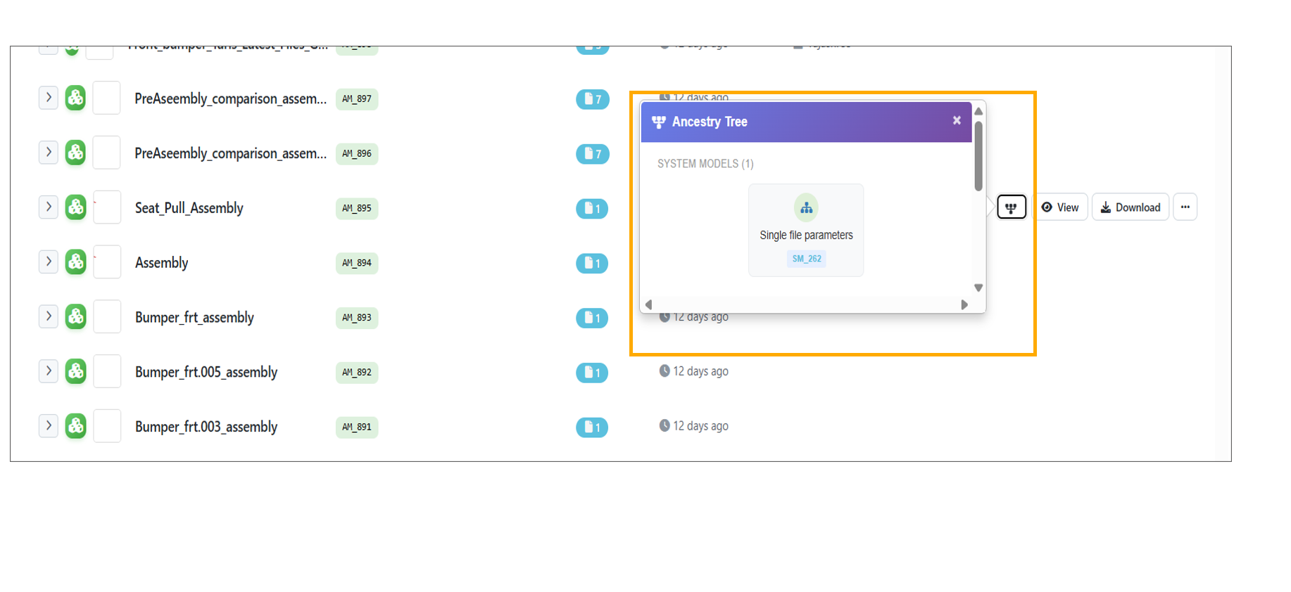
Ancestry tree
13.44. Main file population in workers
*ASSEMBLER_CREATE_SYSTEMMODEL_FROM_ASSEMBLIES worker now automatically generates the main file when an assembly is selected.
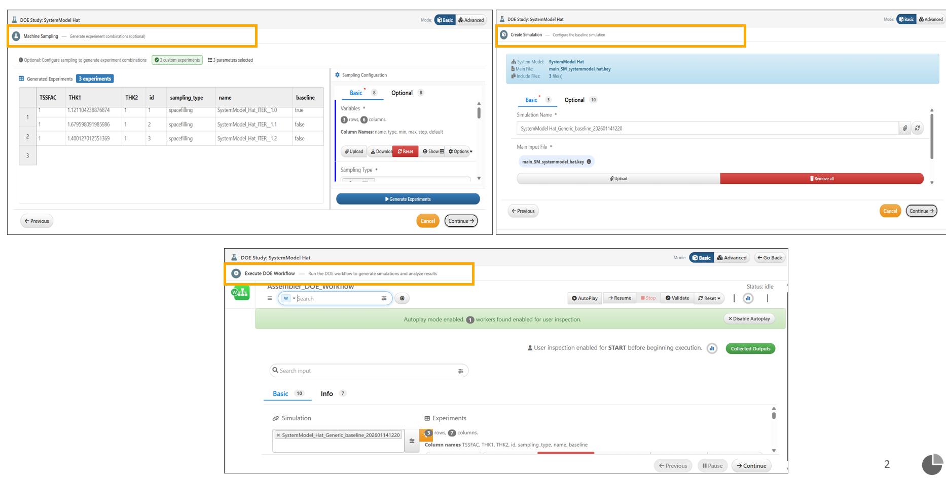
The Run DOE Study workflow now includes a six-step guided flow with a persistent header, enhanced step indicators, and dynamic Basic/Advanced mode switching during workflow execution.
The DOE Parameters table while running DOE now includes right-click context menu with bulk actions such as copying a cell value to all rows and setting all parameters to Constant, Continuous, or Discrete.
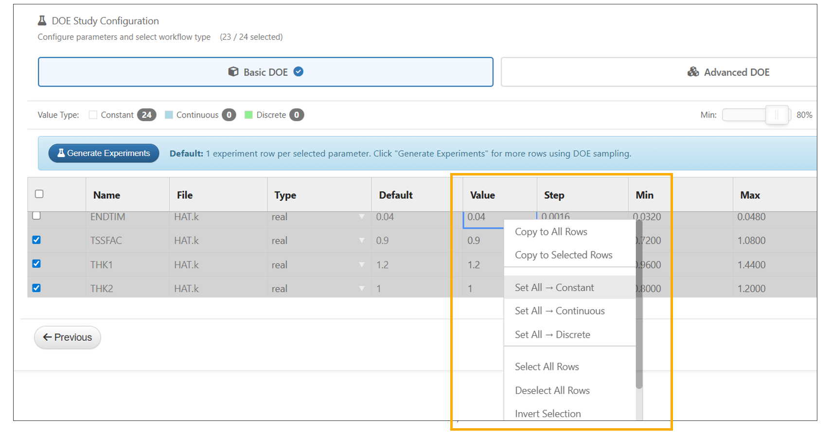
Parameters Context menu options
In the Create DOE modal, uploading a CSV in Upload Custom mode with unmatched column names now automatically opens the Column Mapper. Users cannot proceed without mapping at least one column.
In the DOE submission step from a System Model, CSV and Excel files can now be dragged and dropped into the Custom Parameters upload section, automatically generating a mapper to map file columns.
Create DOE modal is updated to use a persistent header showing the DOE study title, mode toggle and current step details, removing individual step headers in Model Assemblers.
DOE modal Header
In DOE Advanced submission from a System Model, the workflow shows a new Canvas button newly added and present next to Collected Outputs to allow users to switch back to the canvas view.
In DOE submission from a System Model, the Simulation Name in the Configuration tab is now automatically populated with the first experiment name when experiments are generated.
In the system models load case editor for DOE, switching to Template View now has ‘Add Transformations’ option in the right-click menu for assembly files. The transformations added will be shown in the parsed view.
In Model Assembler, the Response Template input is now auto-filled during DOE submission and when a loadcase is dropped into the code editor.
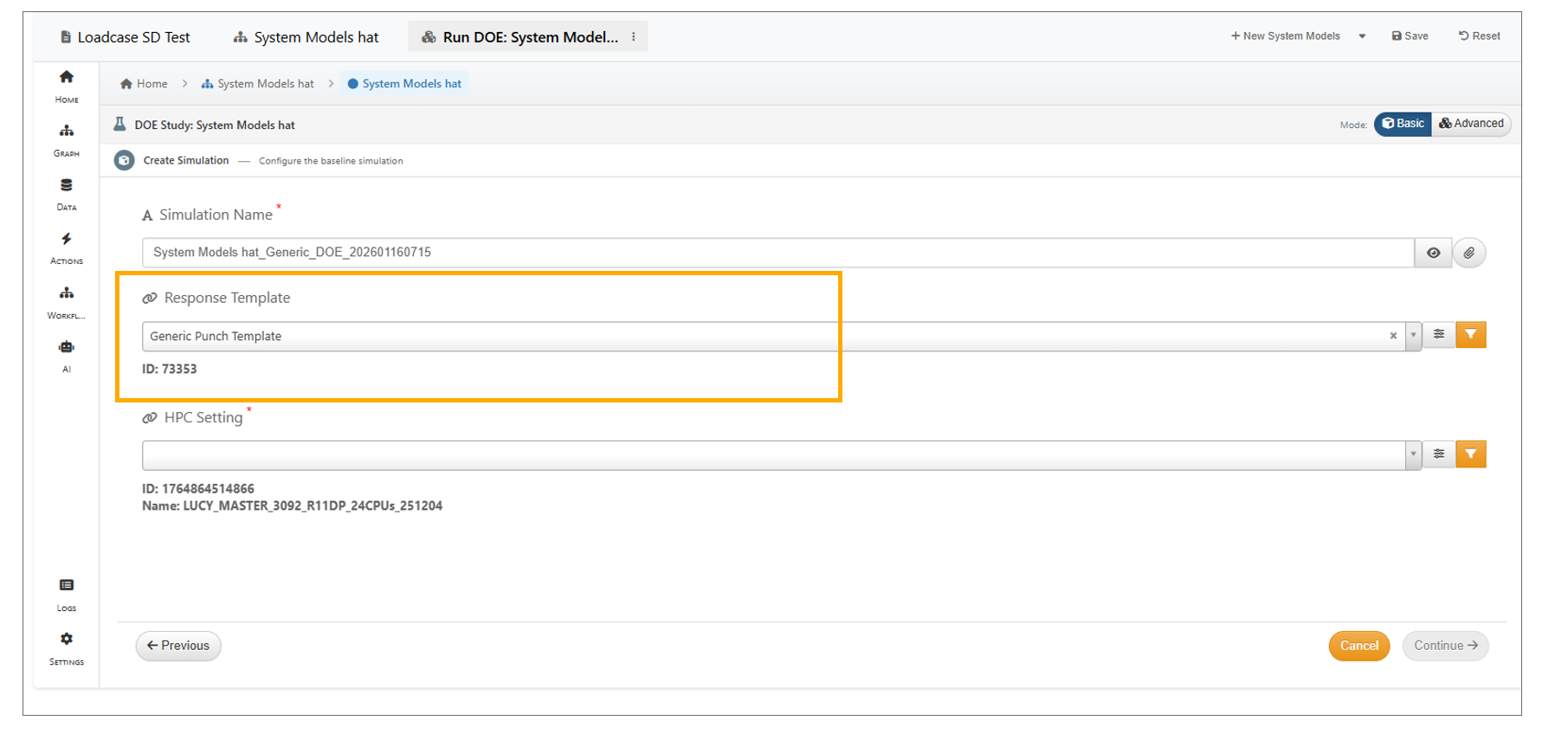
DOE Template selection
In Model Assembler, when submitting a DOE, changes to workflow inputs now trigger actions and automatically update the inputs in AutoPlay mode.
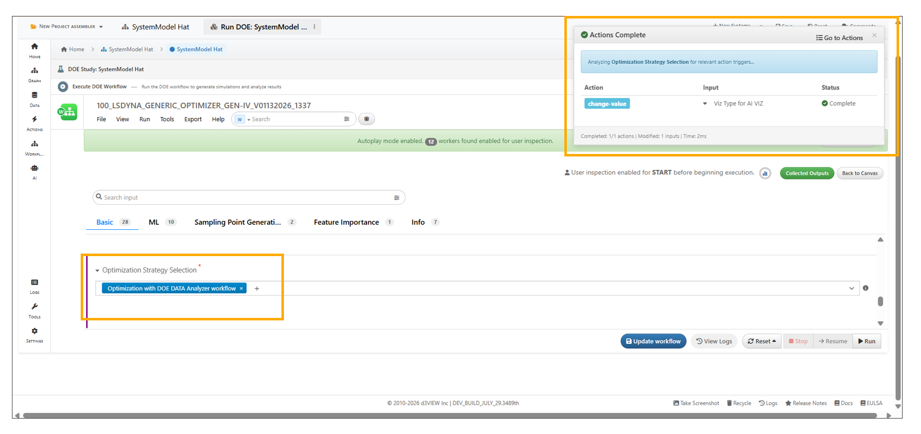
DOE Actions
A new option in Model Assembler → DOE Configuration allows users to choose whether to Attach all files or Attach only parameterized files when submitting DOE simulations. The selected files can be verified in the files included with the submitted DOE simulation.
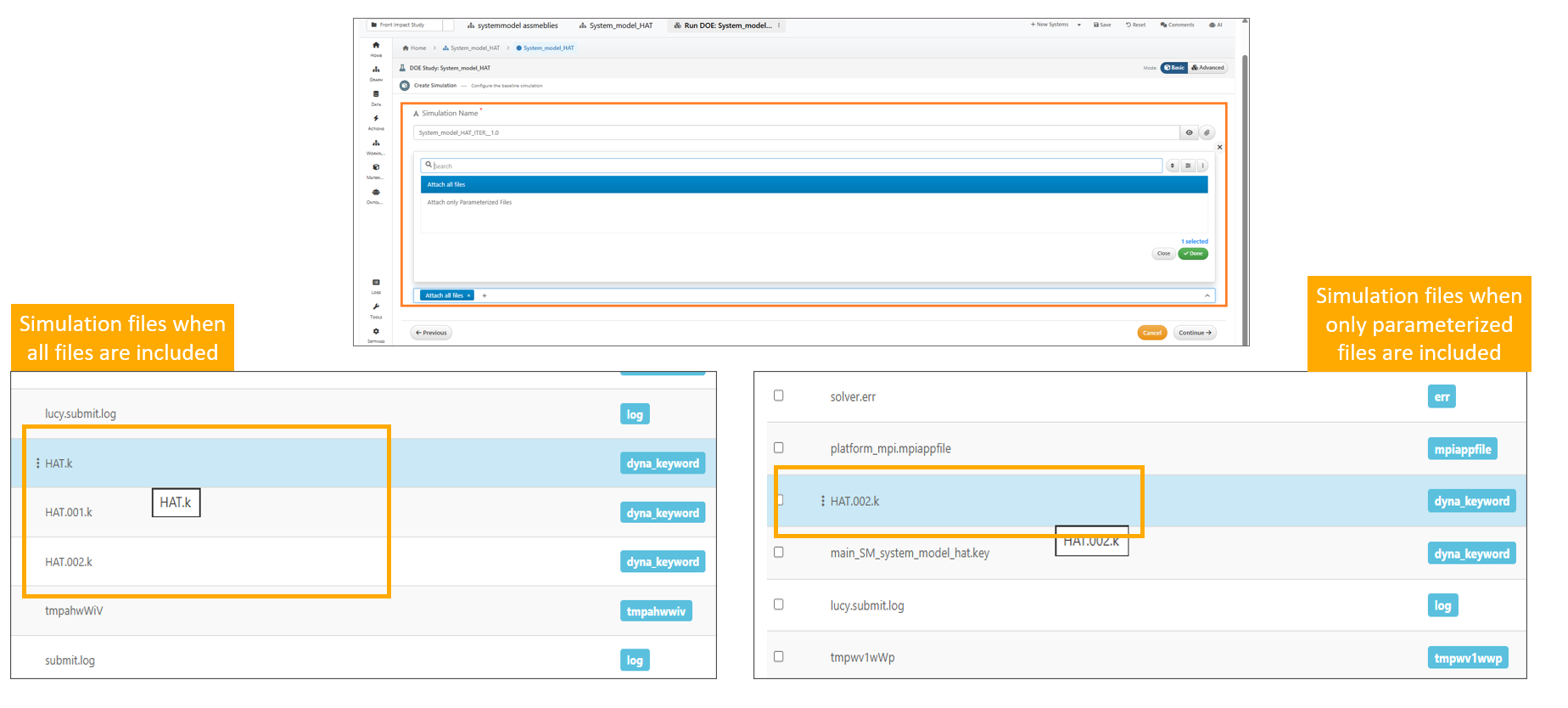
DOE Configuration
13.45. Senors
Sensors can be configured using ‘Configure Sensors’ while submitting the DOE modal after selecting a Response Template, which opens a sensors mapper and saves the configuration to the modal.
Sensors can now be configured using the ‘Configure Sensors’ option when creating a simulation within a Loadcase in Model Assembler.
13.46. Saving of workflow
The workflow is now saved before polling starts while submitting the DOE in Model Assemblers.
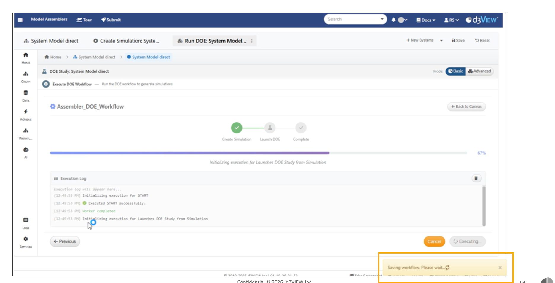
Saving of workflow
Nested structure support for loadcases is now available in the dashboard table view, with expandable Files, Template, and Simulations sections.
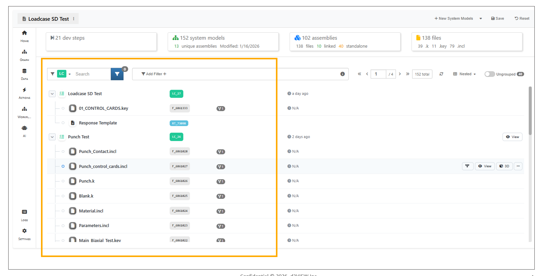
Loadcases page
Model Assembler now shows the simulation count on the Load Case About homepage.
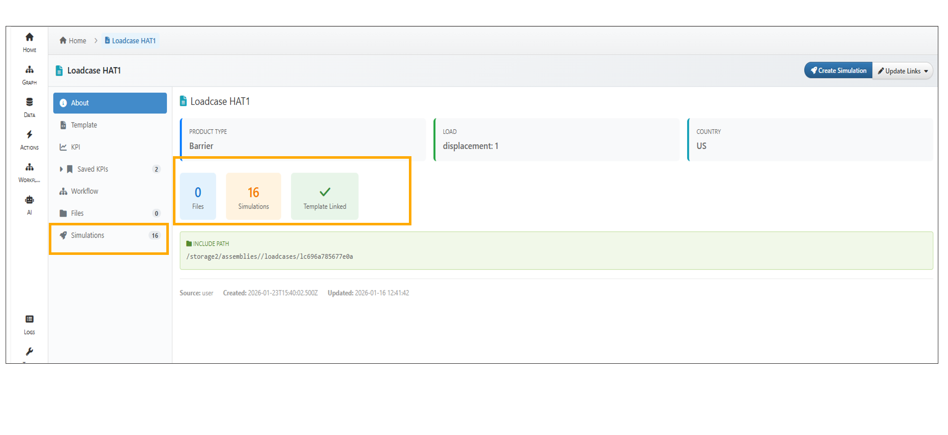
Simulation Count
13.47. Create Simulation
In Model assembler Loadcase, Create Simulation now uses a single merged header showing load case details on the left and a Basic/Advanced toggle with tooltips on the right. The Response Template input is revealed when Configure Template is set to Yes. Advanced simulation creation will execute the workflow after the simulation is created.
13.48. Update links
In Model Assembler, loadcases can now be associated with workflows using Update Links or during workflow creation and viewed from the Workflow tab in the tree view.
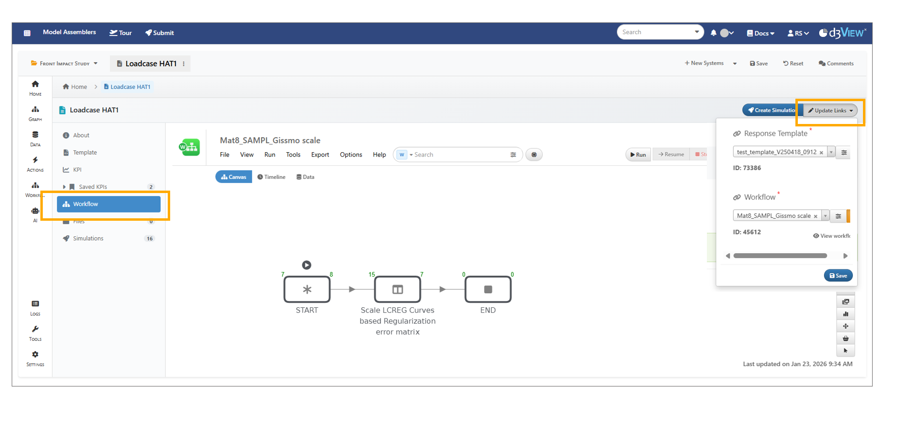
Update links
In Model Assembler, updating links in a Loadcase now shows a ‘Remote Value not available’ message if the template has been removed from the user’s account.’‘
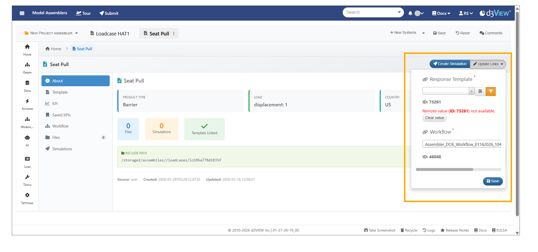
Update links
13.49. Template
The Template tab in Loadcases now shows four summary cards at the top that display counts with clickable links.
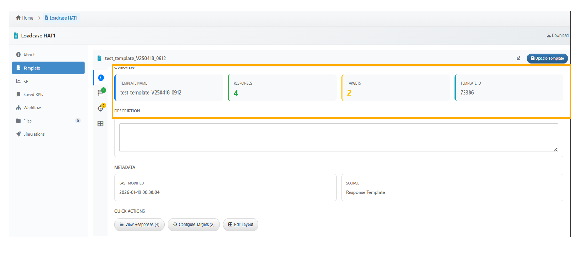
Loadcases summary cards
The template can be modified and updated in a Load Case using the Update Template option in the Model Assembler.
In Loadcase Template tab, the Targets sub-tab now allows users to add targets inline , edit target details (name, scalar response selection, operator, and value) and successfully save all changes using Update Template.
13.50. Files
In Model Assembler, the loadcase files can be deleted using the delete option available under options to the right side of the file.
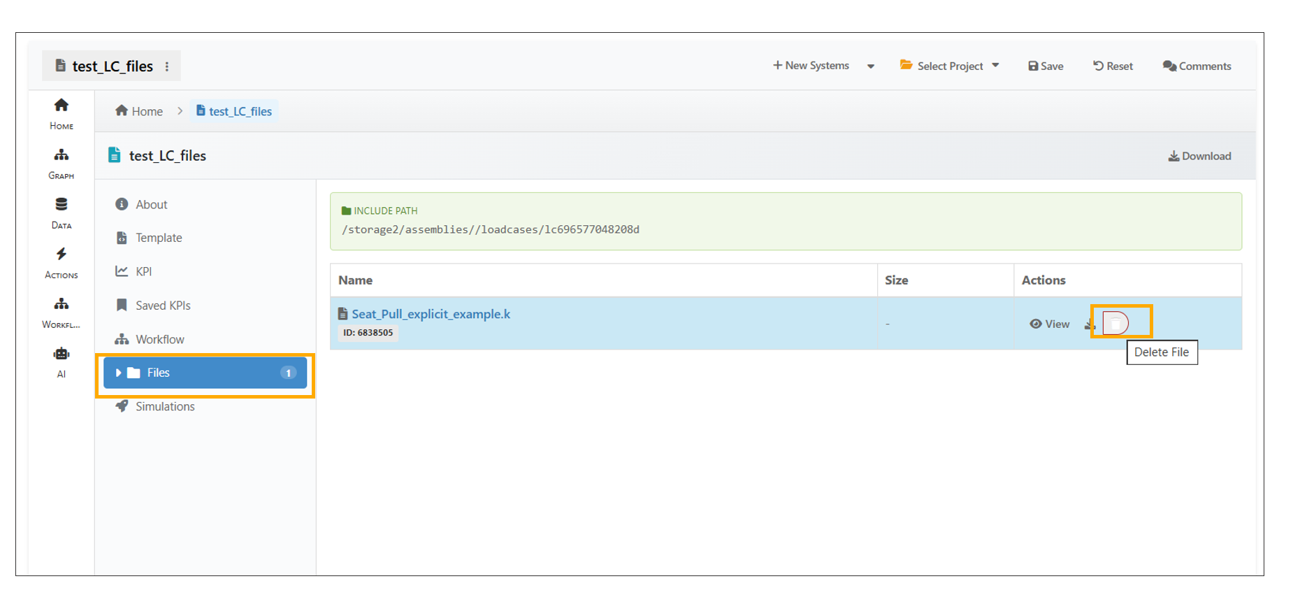
Loadcases Files
In Modal Assembler, a DYNA keyword file added to a System Model can now be viewed in 3D.
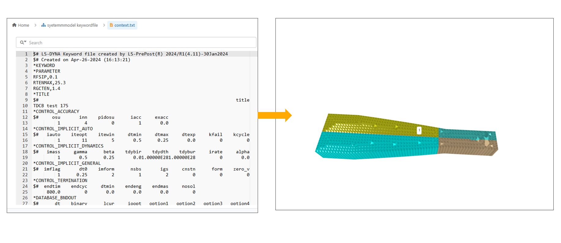
Keyword Files
In Model Assembler, users can now merge selected assembly files into a single timestamped file.
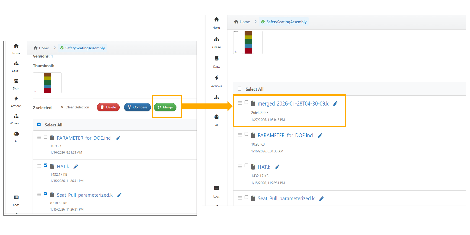
Merge Files
13.51. KPI
The KPI View in a Loadcase now opens Simlytiks in mini view mode, with a Home button in the sidebar for easy navigation. Users can switch to Data Overview and return to the main window using Home button, with all visualizations rendering after switching.
13.52. Response Matrix Comparison
Simulations from loadcases can be compared using the Response Matrix Comparison option, which displays both common and remaining responses across the simulations.
13.53. Migration Assistant
In Model Assembler, the Migration Assistant now allows migrating records to a target project, with search and project filters available in the selection modal.
13.54. Export
In Model Assembler, exporting system models and assemblies is available from the ‘Tools’ tab. Select a project and design step in the ‘Export’ modal, choose records using search or category filters, and export to download a single ZIP file.
Model Assembler export under Tools now supports simulation data. While exporting selected system models, the “Include simulation data” option is available, and the exported ZIP includes simulation_data.json for each selected system model with simulation and response data.
13.56. Color Assignment
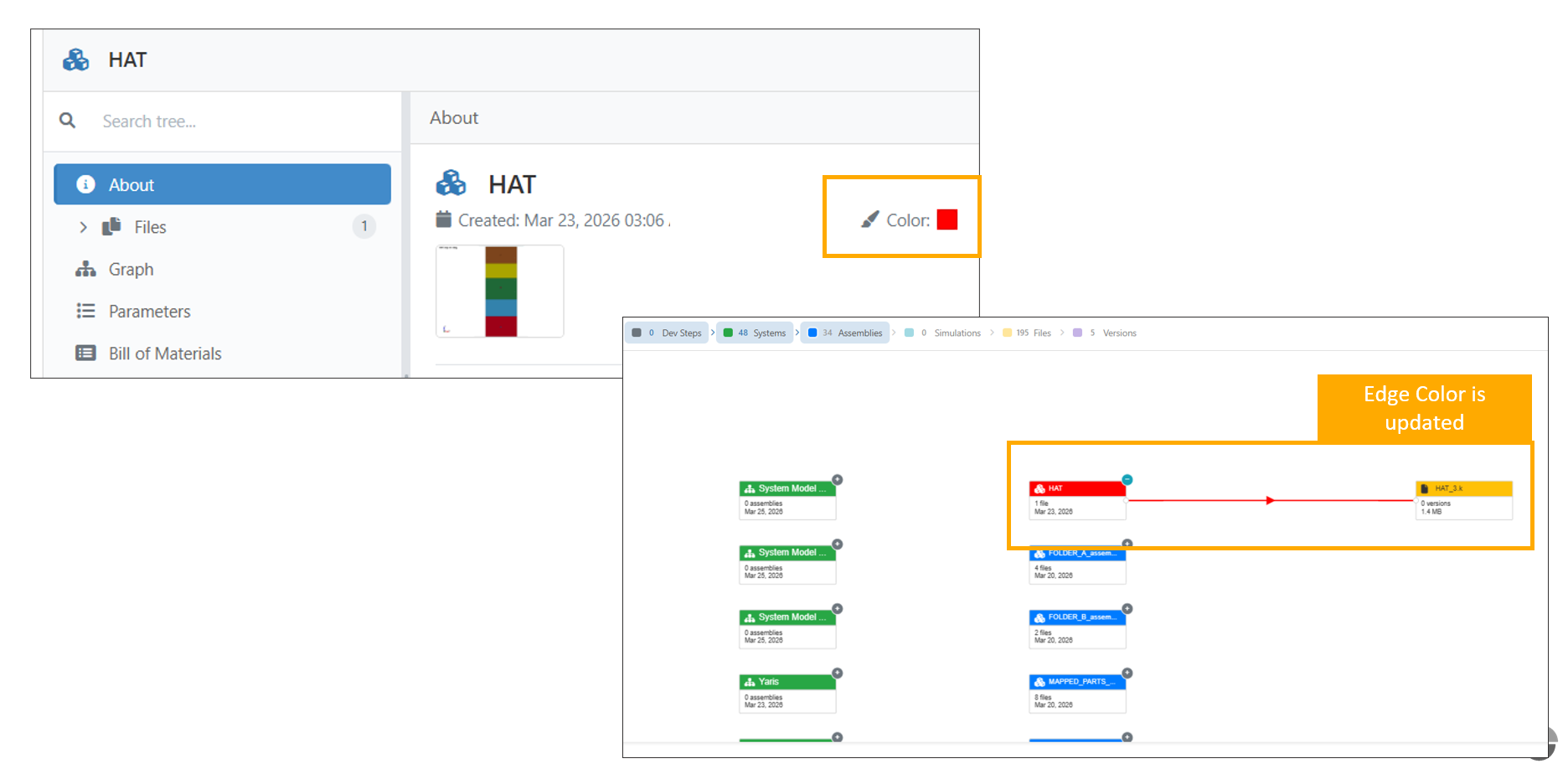
Model Assembler now supports custom color configuration for Assembly and System Models. This enhancement improves visual clarity by allowing users to assign distinct colors to models, with corresponding updates reflected in the graph view.
Key Features Assign custom colors to Assembly and System Models Outgoing graph edges adopt the selected model color Real-time updates in the graph visualization Improved differentiation between model components
Color Assemblers