22. Post-Necking and GISSMO Material Calibration
23. Purpose of the Workflow
Preparing GISSMO Material cards by utilizing material test data. The calibration process can be classified into two parts such as:
1/ Post-necking calibration. 2/ Failure strain vs Triaxiality curve calibration.
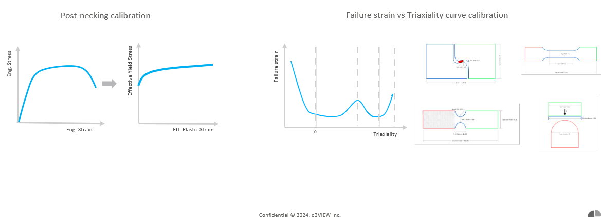
Purpose Workflow
24. Elements of the Workflow
1/ Input data preparation
2/ Verification of material cards
3/ Post-necking calibration
4/ Failure strain calibration
5/ Regularization
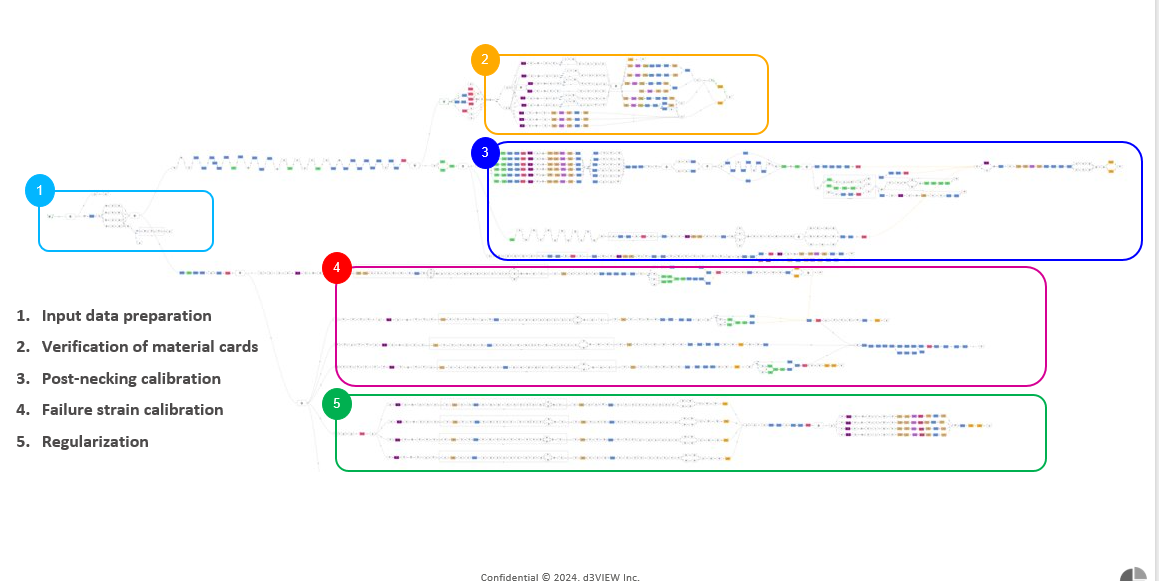
Elements of the Workflows
25. Features of the Workflow
- 1/ Material data input:
- Material data population is now a part of workflow execution which allow us to populate material data with few clicks.
- 2/ Decision Based Execution:
- Based on the decision we make; workflow will auto select the material for calibration and execute the calibration process.
- 3/ Machine learning:
- Workflow will take advantage of machine learning methods whenever necessary to reduce the computational time.
- 4/ Report Generation:
- Workflow generates a report for the execution of any calibration process we select.
26. Interaction in Start worker
The only interaction is with the START worker to provide necessary inputs followed by execution of the Workflow.
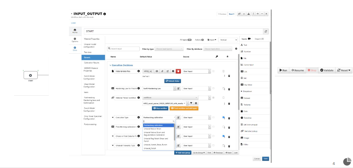
Start worker interaction
Start worker Required Inputs Table.
List of non required inputs in Start worker
Material Type Uniaxial Engineering stress vs strain E8 EMOD MAT_ID Density Poisson’s_Ratio Offset Stress Scale Factor Uniaxial Force Dispalcement E8 Uniaxial Engineering stress vs strain Regularization FD Uniaxial FD Extenention FD EXTENDED Uniaxial E8 GRIP SIZE ENDTOEND Uniaxial E8 Gauge Width Uniaxial E8 Extensometer Length Uniaxial E8 Thickness Uniaxial E8 Gauge Length Plastic_Strain_VS_Displacement Uniaxial E8 DIC VS Displacement Uniaxial E8 FD all specimens Uniaxial E8 DIC vs Displacement all specimens Uniaxial E8 Engg Stress Strain all specimens Uniaxial E8 Specimen Dimension Uniaxial E8 Test Specimen Notch Specimen Thickness Notch Specimen Grip Distance Notch Specimen Gauge Width Notch Specimen Extensometer Length Notch FD all specimens Notch FD test data Notch DIC vs Displacement Notch DIC vs Displacement all specimens Notch Specimen Gauge Length Notch Specimen Dimensions Notch Test Specimen Shear Specimen Gauge Width Shear Specimen Gauge Length Shear FD all specimens Shear_Specimen_Thickness Shear FD test data Shear DIC vs Displacement Shear DIC vs Displacement all specimens Shear Specimen Dimensions Shear Test Specimen Punch Diameter Punch Specimen Diameter Punch FD all specimens Punch Specimen Thickness Punch FD test data Punch DIC vs Displacement all specimens Max Displacement Punch Specimen Gauge Length Punch DIC vs Displacement all specimens Failure Punch Specimen Dimensions Uniaxial Regularization Gauge Width Uniaxial Regularization Extensometer Length Uniaxial Regularization Thickness Uniaxial Regularization Gauge Length Uniaxial Regularization Engineering Stress Strain all specimen Uniaxial Regularization FD all specimen Uniaxial Regularization DIC VS Displacement Uniaxial Regularization DIC vs Displacement all specimens Uniaxial Regularization GRIP SIZE ENDTOEND Uniaxial Regularization Specimen Dimension Uniaxial Regularization Test Specimen Cone Push All Specimen Drop Tower All Specimen Test Triaxiality Curve Material data files Material Parser workflow Execution Type Uniaxial Triaxiality Type Uniaxial Specimen Type Notch Specimen Type Shear Specimen Type Punch 1mm Specimen Type Punch 2mm Specimen Type Cone Push 1mm Specimen Type Cone Push 3mm Specimen Type Drop Tower 2mps Specimen Type Drop Tower 4mps Specimen Type Punch 3mm Specimen Type d3VIEW Uniaxial Specimen d3VIEW Shear Specimen d3VIEW Punch Specimen Notch Custom Specimen File Shear Custom Specimen File Punch_Custom_Specimen 1mm Cone Push Custom Specimen 1mm Cone Push Custom Specimen 2mm Drop Tower Custom Specimen 2mps Punch Custom specimen 2mm Punch Custom specimen 3mm Uniaxial Template d3VIEW Uniaxial_Solver_Config Notch Solver Config Shear Solver Config Punch Solver Config Preliminary Hardening Curve Calibrated Hardening Curve MAT24 with Calibrated Hardening curve Strain Rate Curves Table Strain Rate Table ECRIT Curve Calibrated LCSDG Curve Calibrated LCREGD curve Calibrated FADEXP curve Uniaxial Failure Strain calibration curve Punch Failure Strain calibration curve Notch Failure Strain calibration curve Shear Failure Strain calibration curve Notch Shadow Triaxiality Shear Shadow Triaxiality Biaxial Shadow Triaxiality Punch Domain Range 1 Baseline LCSREG FD Extension Notch FD EXTENDED_Notch FD Extension Shear FD EXTENDED_Shear MAT_ADD_EROSION_Calibrated FD EXTENDED_Punch Initial K value Yield Strength Ultimate Tensile Strength Strain Rate Failure Curve Element location for Punch Max displacement Shear Element location Max displacement Notch Center location Element for Max Strain Center Element location Uniaxial E8 Max Strain Center Element location for Uniaxial Reg Max Strain Uniaxial E8 Specimen PID Uniaxial Reg Specimen PID Biaxial Specimen PID Shear Specimen PID Notch Specimen Part ID Uniaxial E8 Ext Node 1 Uniaxial E8 Ext Node 2 Uniaxial E8 Width Node 2 Uniaxial E8 Width Node 1 Archived files Uniaxial E8 Specimen Dimensions Comparison Threshold min Uniaxial E8 Specimen Dimensions Comparison Threshold max Uniaxial Reg Ext Node 1 Uniaxial Reg Ext Node 2 Uniaxial Reg Width Node 1 Uniaxial Reg Width Node 2 Uniaxial Regularization Specimen Dimensions Comparison Threshold min Uniaxial Regularization Specimen Dimensions Comparison Threshold max Notch Ext Node 1 Notch Ext Node 2 Notch Width Node 1 Notch Radius node 1 Notch Width Node 2 Notch Radius node 2 Notch Radius node 3 Notch Specimen Dimensions Comparison Threshold min Notch Specimen Dimensions Comparison Threshold max Shear Width Node 1 Shear Width Node 2 Shear Length Node 1 Shear Length Node 2 Shear Ext Node 1 Shear Ext Node 2 Shear Specimen Dimensions Comparison Threshold max Shear Specimen Dimensions Comparison Threshold min Punch Node 1 Punch Node 2 Punch Node 3 Biaxial Blank Node 1 Biaxial Blank Node 2 Biaxial Blank Node 3 Biaxial Die Node 1 Biaxial Die Node 2 Biaxial Die Node 3 Biaxial Specimen Dimensions Comparison Threshold min Biaxial Specimen Dimensions Comparison Threshold max Reporter Template
Workflow execution with simple steps
We can calibrate a material by executing the workflow as described below.
- 1/ Navigate to ‘Generic’ in the Start worker:
- The generic tab holds all the ‘Execution Decisions’ one might need to take.
2/ After attaching ‘Material data file’ we can set the Execution type to ‘Get data from material parser’
- 3/ Once we have all the material data, we can execute the workflow by setting the ‘Execution type’ to below settings in the given order.
- a.Verification : Verification with Uncalibrated MAT24 and Uncalibrated failure
- b.Post-necking calibration : FD based
- c.Failure Strain calibration: Uniaxial Notch Shear and Punch
- d.Regularization
27. Calibrated MAT24 card
This workflow is constructed to take an Engineering Stress Strain curve and provide a calibrated MAT24 card whose material behaviour up until and including the Post necking region is similar to that of the Test data.
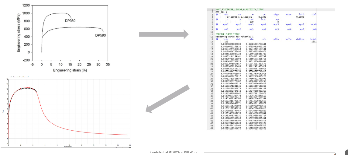
Calibrated MAT24 card
28. Flow of the Workflow
The below image shows the flow of the GISSMO Workflow.
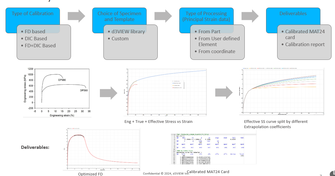
Flow of the Workflow
29. Post Simulation Results
The PPT report should have already been rendered and stored. Results can be downloaded from the PPT blob.
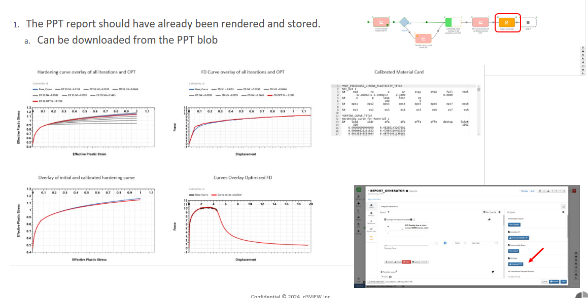
PPT Results
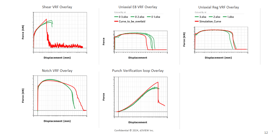
30. GISSMO Material Calibration with MAT_ADD_EROSION
LCSDG Curve From Test
1/ d3VIEWs Material excel parser help us extract all the material information that we need for the calibration process. 2/ This includes the extraction of failure strain from the available DIC strain data. 3/ Material excel parser prepares the Failure Strain vs triaxiality curve which becomes the starting point for the failure calibration process.
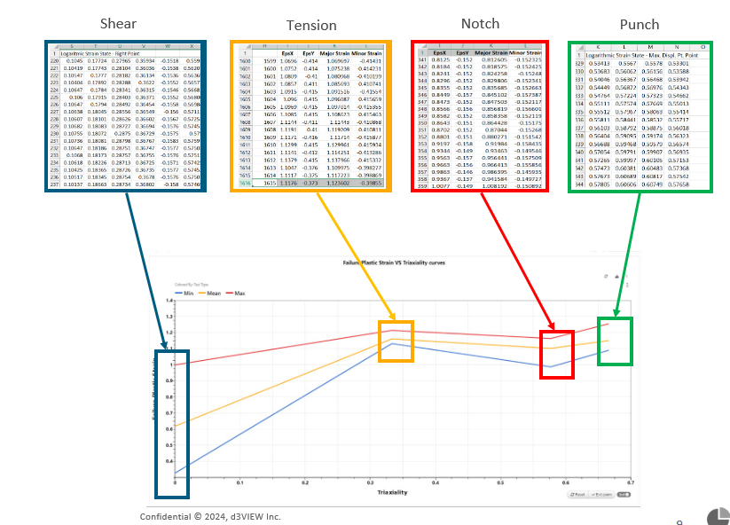
LCSDG Curve From Test
30.1. 1/ LCSDG Curve Calibration
- We can calibrate the LCSDG curve with two ways
- Failure Strain calibration with reference triaxiality (0, 0.333, 0.567, 0.666).
- Failure strain calibration along with the triaxiality at failure (adding the triaxiality at failure point along with the reference triaxility).
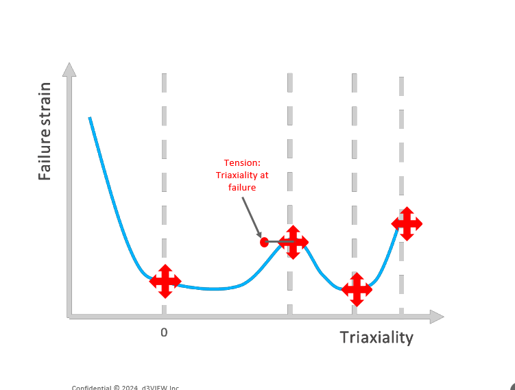
LCSDG Curve Calibrartion
30.2. 2/ LCREG and FADEXP Curve Calibration
LCREG and FADEXP Curve Calibration
Once we have the calibrated LCSDG curve, the next steps involved in the calibration process is to calibrate the FADEXP and LCREG curves. We calibrate these curves simultaneously by optimizing the LCREG and FADEXP factors for each mesh size and then consolidating the curves.
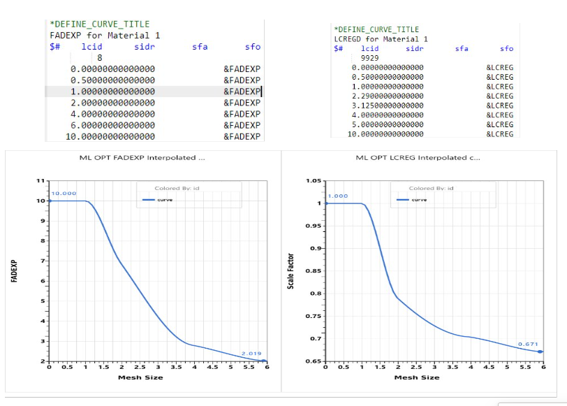
LCSDG and FADEXP Curve Calibrartion